Bryant LEGACY 580J*20M Series Installation Instructions Manual Download Page 54

Manufacturer reserves the right to change, at any time, specifications and designs without notice and without obligations.

Replaces: II580J-17-30-V-02

Copyright 2018 Bryant Heating & Cooling Systems

Edition Date: 4/18

Printed in U.S.A

Catalog No: II580J–17-30-V–03

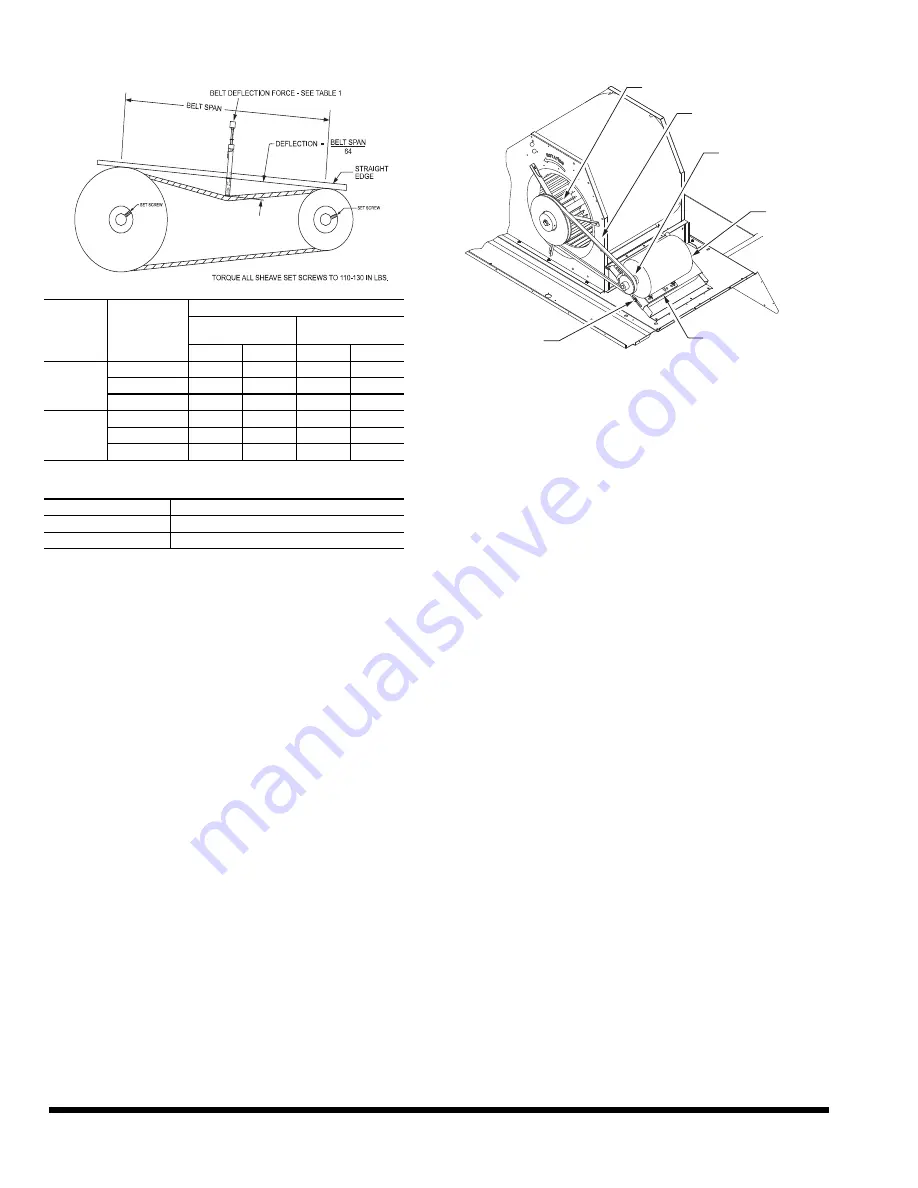
Fig. 65 — V-Belt Force Label

Fig. 66 — Belt Drive Motor Mounting

Pre-Start and Start-Up — 

This completes the mechanical in-

stallation of the unit. Refer to the unit’s Service Manual for detailed

Pre-Start and Start-Up instructions. Download the latest versions

from HVAC Partners (www.hvacpartners.com).

Table 1

Table 2

BELT 

CROSS 

SECTION

SMALLEST 

SHEAVE 

DIAMETER

BELT DEFLECTION FORCE (LBS)

UNNOTCHED 

BELTS

NOTCHED BELTS

USED

NEW

USED

NEW

A, AX

3.0-3.6

3.7

5.5

4.1

  6.1

3.8-4.8

4.5

6.8

5.0

  7.4

5.0-7.0

5.4

8.0

5.7

  8.4

B, BX

3.4-4.2

4.9

  7.2

4.4-5.6

5.3

7.9

7.1

10.5

5.8-8.6

6.3

9.4

8.5

12.6

BELT CONDITION

TENSION FORCE IN BELT (LBS)

New

100

Used

80

BLOWER PULLEY

V-BELT

MOTOR 

PULLEY

MOTOR

MOTOR MOUNTING

PLATE 

MOUNTING

BOLTS (4) 

Summary of Contents for LEGACY 580J*20M Series

Page 1: ...in severe personal injury or death WARNING signifies hazards which could result in personal injury or death CAUTION is used to identify unsafe practices which may result in minor personal injury or p...

Page 2: ...uilding Check that all openings in the outside wall around the vent and air intake pipe s are sealed to prevent infiltration of combustion products into the building Check that furnace vent and air in...

Page 3: ...u H Al Al Cu Cu J Al Al E coat Al Cu K E coat Al Al Al Cu L E coat Al Al E coat Al Cu T Al Al Al Cu Louvered Hail Guards U Al Al Cu Cu Louvered Hail Guards V Al Al E coat Al Cu Louvered Hail Guards W...

Page 4: ...4 Fig 2 Unit Dimensional Drawing 17 and 20 Size Unit...

Page 5: ...5 Fig 2 Unit Dimensional Drawing 17 and 20 Size Unit cont...

Page 6: ...6 Fig 3 Unit Dimensional Drawing 24 and 28 Size Unit...

Page 7: ...7 Fig 3 Unit Dimensional Drawing 24 and 28 Size Unit cont...

Page 8: ...8 Fig 4 Unit Dimensional Drawing 30 Size Unit...

Page 9: ...9 Fig 4 Unit Dimensional Drawing 30 Size Unit cont...

Page 10: ...iation 54 TIA 54 84 1 In Canada installation must be in accordance with the CAN1 B149 installation codes for gas burning appliances Although unit is weatherproof avoid locations that permit water from...

Page 11: ...n closed position Locate the carton containing the outside air hood parts in the rear blower assembly Do not remove carton until unit has been rigged and located in final position Step 4 Provide Unit...

Page 12: ...eeper rails cannot be used support the long sides of the unit with a minimum of 4 equally spaced 4 in x 4 in 102 mm x 102 mm pads on each side Lo cate pads so that they support the rails Make sure to...

Page 13: ...13 Fig 8 Roof Curb Details 17 and 20 Size Units 17 20...

Page 14: ...14 Fig 9 Roof Curb Details 24 and 28 Size Units 24 28...

Page 15: ...15 Fig 10 Roof Curb Details 30 Size Units 30...

Page 16: ...he condenser end of the unit being approximately equal to Details A and B in Fig 8 10 Do not attempt to slide unit on curb after unit is set Doing so will result in damage to the roof curb seal Althou...

Page 17: ...the four angles installed in Step 2 Make sure that the screens extend across the entire length of the hood 8 Install side filter supports using the screws provided 9 Install side drip angles using the...

Page 18: ...ations gas pressure at unit gas connec tion must not be less than 5 in wg 1246 Pa or greater than 13 in wg 3240 Pa while the unit is operating see Table 3 Table 3 Natural Gas Supply Line Pressure Mani...

Page 19: ...mal damage Support all piping with appropriate straps hangers etc Use a minimum of one hanger every 6 ft 1 8 m For pipe sizes larger than 1 2 in follow recom mendations of national codes 3 Apply joint...

Page 20: ...tch operation of the convenience outlet is desired connect the source leads to the load side of the unit disconnect On a unit without a unit mounted disconnect connect the source leads to the line sid...

Page 21: ...crew to secure the shaft to the NFD 6 Turn the handle to OFF position with red arrow pointing at OFF 7 Install the handle on to the corner post vertically with the red arrow pointing up 8 Secure the h...

Page 22: ...e 125 volt 15 A circuit powered from a source else where in the building Observe national and local codes when se lecting wire size fuse or breaker requirements and disconnect switch size and location...

Page 23: ...n for Building Management Systems using non CCN protocols RTU Open is available as a factory installed option only Thermostat Install a Bryant approved accessory 2 stage ther mostat according to insta...

Page 24: ...t for dehumidification control The humidistat is nor mally used in applications where a temperature control is already provided such as a third party Building Management System To connect a field supp...

Page 25: ...25 Fig 33 Typical Perfect Humidity Adaptive Dehumidification System Humidistat Wiring...

Page 26: ...s checkout tests and alarm and error conditions with a 2 line 16 character LCD display and four button keypad Electrical Rated Voltage 20 to 30 Vac RMS 50 60 Hz Transformer 100 va maximum system input...

Page 27: ...ut e g CO2 sensor IAQ COM COM Air Quality Sensor Common IAQ 24V 24 vac Air Quality Sensor 24 vac Source ACT 2 10 2 10 vdc Damper Actuator Output 2 10 vdc ACT COM COM Damper Actuator Output Common ACT...

Page 28: ...o display the first item in the currently displayed menu Fig 38 W7220 Controller Menu Buttons Press the Menu Up Exit button to exit a menu s item and return to the list of menus To use the keypad when...

Page 29: ...COOLING DEMAND Y1 IN Y1 I signal from space thermostat or unitary controller for cooling stage 1 ON 24 Vac on terminal Y1 I OFF 0 Vac on terminal Y1 I COOL Y1 OUT OFF ON OFF FIRST STAGE COOLING RELAY...

Page 30: ...NOT connected VENTMAX With 2 speed fan units VENTMAX L low speed fan and VENTMAX H high speed fan settings are required 2 8 V 2 to 10 Vdc DCV MAXIMUM DAMPER POSITION Displays only if a CO2 sensor is...

Page 31: ...ory defaults when set to YES LCD will briefly flash YES and change to NO but all parameters will change to the fac tory default values NOTE RECHECK AUX2 IN and FANTYPE for required 2 speed values ADVA...

Page 32: ...r signals an ERV that the conditions are not good for economizing but are for ERV operation SYS 24 Vac out Issues a system alarm CONNECT EXH1 N A N A Closes the power exhaust fan 2 relay EXH1 ALARMS A...

Page 33: ...ble 11 For 1 speed fan dry bulb and en thalpy operation with and without DCV see Tables 12 15 For 2 speed fan dry bulb and enthalpy operation with and without DCV see Tables 16 19 Table 11 Damper Mini...

Page 34: ...On 0v Off MIN POS to Full Open Closed to Full Open DEMAND CONTROLLED VENTILATION DCV OUTSIDE AIR GOOD TO ECONOMIZE Y1 I Y2 I FAN SPEED Y1 O Y2 O OCCUPIED UNOCCUPIED Below CO2 Set No OFF OFF HIGH 0v Of...

Page 35: ...0v Off VENTMIN Closed ON OFF HIGH 0v Off 0v Off VENTMIN to Full Open Closed to Full Open ON ON HIGH 24v On 0v Off VENTMIN to Full Open Closed to Full Open Above CO2 Set No OFF OFF HIGH 0v Off 0v Off...

Page 36: ...0v Off VENTMIN Closed ON OFF LOW 0v Off 0v Off VENTMIN to Full Open Closed to Full Open ON ON HIGH 24v On 0v Off VENTMIN to Full Open Closed to Full Open Above CO2 Set No OFF OFF LOW 0v Off 0v Off VEN...

Page 37: ...s There is also a high limit boundary for differential enthalpy The high limit boundary is ES1 when there are no stages of mechanical cooling energized and HL high limit when a compressor stage is ene...

Page 38: ...s devices and sensors configured NOTE See Interface Overview on page 28 for information about menu navigation and use of the keypad Checkout Tests Use the Checkout menu in Table 10 to test the damper...

Page 39: ...pular protocols in use today BACnet1 Modbus2 Johnson N2 and LonWorks3 see Fig 41 and 42 Refer to Table 22 RTU Open Controller Inputs and Outputs for locations of all connections to the RTU Open board...

Page 40: ...40 Fig 41 Typical RTU Open System Control Wiring Diagram...

Page 41: ...41 Fig 42 Typical RTU Open System Control Wiring Diagram with Perfect Humidity System...

Page 42: ...24 VAC J5 7 8 Binary Input 9 Zone Temperature n a n a J13 1 4 Rnet CONFIGURABLE INPUTS4 Indoor Air CO2 iaq AI 4 20 mA J4 2 3 or J4 5 6 Analog Input 2 Outdoor Air CO2 oaq AI 4 20 mA Analog Input 1 Spa...

Page 43: ...trol wires through the hole provided in the corner post then feed the wires thorough the raceway to the RTU Open Connect to the wires to the removable Phoenix connectors and then reconnect the connect...

Page 44: ...upplied with the CO2 sensor for electrical requirements and ter minal locations See Fig 49 for typical CO2 sensor wiring sche matic To accurately monitor the quality of the air in the conditioned air...

Page 45: ...istat NOTE The accessory space relative humidity sensor and hu midistat do not apply to size 30 units Perfect Humidity Control Wiring In units equipped with the Perfect Humidity 580J option there are...

Page 46: ...ote occupancy accessory is a field installed accessory This accessory overrides the unoccu pied mode and puts the unit in occupied mode When installing this accessory the unit must be configured for r...

Page 47: ...the communication LEDs see Fig 40 The LEDs indicate if the controller is speaking to the devices on the network The LEDs should reflect communication traffic based on the baud rate set The higher the...

Page 48: ...t Connect to the Local Access port USB Link Kit RTU Open Controller Access Port J12 P1 P1 P5 P5 LOCAL ACCESS PORT GND GND Therm mA Therm mA UI 10 UI 11 SW3 on COMM OPTION CR2032 SW1 SW2 MSB LSB TX RX...

Page 49: ...the return air sensor module housing which protrudes through the back of the control box Fig 61 Typical Supply Air Smoke Detector Sensor Location Fig 62 Return Air Sampling Tube Location in Unit witho...

Page 50: ...ine maximum deviation from average voltage AB 227 224 3 v BC 231 227 4 v AC 227 226 1 v Maximum deviation is 4 v Determine percent of voltage imbalance This amount of phase imbalance is satisfactory a...

Page 51: ...25 124 560 114 0 113 1 150 150 117 116 545 125 8 124 9 150 150 131 130 565 MED High 112 7 150 116 536 124 5 150 129 556 117 5 150 121 541 129 3 175 135 561 HIGH High 124 1 150 129 615 135 9 175 142 63...

Page 52: ...40 8 50 43 222 37 7 45 40 216 42 5 50 45 224 580J 24 208 230 1 60 STD 109 2 108 3 150 150 112 111 540 121 0 120 1 150 150 125 124 560 114 0 113 1 150 150 117 116 545 125 8 124 9 150 150 131 130 565 ME...

Page 53: ...te installation instructions for information on installing these accessories Step 14 Check Belt Tension Measure the belt span length as shown in Fig 65 Calculate the required deflection by multiplying...

Page 54: ...of the unit Refer to the unit s Service Manual for detailed Pre Start and Start Up instructions Download the latest versions from HVAC Partners www hvacpartners com Table 1 Table 2 BELT CROSS SECTION...

Page 55: ...Y N _____ Verify that unit installation is level Y N _____ Check fan wheels and propeller for location in housing orifice and setscrew tightness Y N _____ Check to ensure that electrical wiring is not...

Page 56: ...charge pressure _______________ PSIG C Entering air temperature _______________ F D Liquid line temperature at outlet or reheat coil _______________ F E Confirm correct rotation for compressor Y N ___...

Reviews: