a. LED flashes a fault code 4 times. Record this fault code for further troubleshooting.
b. Inducer motor starts and continues to run the entire component test.
c. Hot surface ignitor is energized for 15 sec, then de-energized.
d. Main blower operates at cooling speed for 10 sec, then turns off.
e. Main blower operates at heating speed for 10 sec, then turns off.
f. Inducer motor stops.
Items a through e above will assist in furnace troubleshooting since all components are functionally operated except the gas valve. This
procedure is also referred to as "Component Test."
3. Operate furnace through 1 heat cycle to test for proper operation and check LED status.
4. If furnace is operating properly and LED indicates proper operation, replace control access door.
5. Component Test can also be initiated by performing the following:
a. Remove control access door.
b. Remove blower access door.
c. Manually close blower access door switch.
WARNING: Blower access door switch opens 115-v power to control center. No component operation can occur.
Caution must be taken when manually closing this switch for service purposes. Failure to follow this warning could result
in personal injury or death.
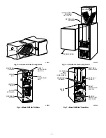
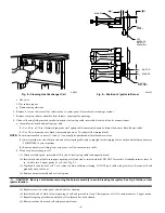
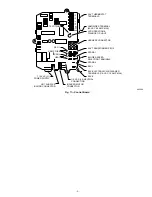
d. BRIEFLY short (jumper) TEST, 1/4-in. quick-connect terminal on control center (adjacent to LED diagnostic light), and Com terminal
on thermostat connection block. (See Fig. 11.)
NOTE:
If TEST to Com terminals are jumpered longer than 2 sec, LED will flash rapidly, and retrieval request will be ignored.
e. Component Test will function as described in item 2 above.
f. Check LED status.
g. If LED status indicates proper operation, release blower access door switch, replace blower access door, and replace control access door.
E.
Troubleshooting
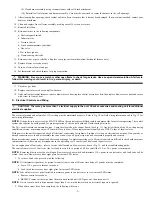
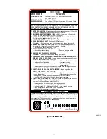
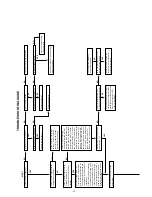
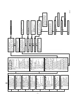
Refer to the service label. (See Fig. 13.) Pages 12 and 13 contain a troubleshooting guide. This guide can be a useful tool in isolating furnace
operation problems. Beginning with the word "Start," answer each question and follow the appropriate arrow to the next item.
The guide will help to identify the problem or failed component. After replacing any component, verify correct operation sequence.
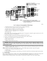
Fig. 10—Heating and Cooling Application Wiring Diagram
A95241
115-VOLT FIELD-
SUPPLIED
FUSED
DISCONNECT
AUXILIARY
J-BOX
CONTROL
BOX
24-VOLT
TERMINAL
BLOCK
THREE-WIRE
HEATING-
ONLY
FIVE
WIRE
NOTE 1
NOTE 2
FIELD-SUPPLIED
FUSED DISCONNECT
CONDENSING
UNIT
TWO
WIRE
FURNACE
R
G
C
W
C
R
G
Y
GND
GND
FIELD 24-VOLT WIRING
FIELD 115-, 208/230-, 460-VOLT WIRING
FACTORY 24-VOLT WIRING
FACTORY 115-VOLT WIRING
208/230- OR
460-VOLT
THREE
PHASE
208/230-
VOLT
SINGLE
PHASE
WHT
BLK
WHT
BLK
NOTES:
Connect Y-terminal as shown for proper operation.
Some thermostats require a "C" terminal connection as shown.
If any of the original wire, as supplied, must be replaced, use
same type or equivalent wire.
W
Y
GND
THERMOSTAT
TERMINALS
1.
2.
3.
—8—
Summary of Contents for GB1AAV
Page 15: ...15...


