background image

13

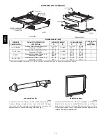
RETURN AIR TEMPERATURE

This furnace is designed for continuous return--air minimum temperature of 60

_

F (15

_

C) db or intermittent operation down to 55

_

F (13

_

C)

db such as when used with a night setback thermometer. Return--air temperature must not exceed 80

_

F (27

_

C) db. Failure to follow these

return air limits may affect reliability of heat exchangers, motors and controls.

60

80

/ 27

˚

C

/ 16

˚

C

SUPPLY AIR

A10490

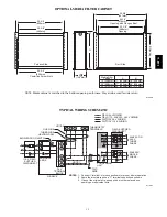
MINIMUM CLEARANCES TO COMBUSTIBLE MATERIALS

POSITION

CLEARANCE

Rear

0 (0 mm)

Front (Combustion air openings in furnace and in structure)

1 in. (25 mm)

Required for service**

24 in. (610 mm)*

All Sides of Supply Plenum**

1 in. (25 mm)

Sides

0 (0 mm)

Vent

0 (0 mm)

Top of Furnace

1 in. (25 mm)

* Recommended
**Consult your local building codes

COMBUSTION--AIR PIPE FOR NON--DIRECT (1--PIPE) VENT APPLICATION

FIELD-SUPPLIED
2-IN. (51 mm) DIA.
PVC PIPE

FIELD-SUPPLIED
2-IN. (51 mm) DIA.
MITERED RADIUS
PVC 90

°

 ELBOW

12” (300 mm) MINIMUM

A12376

NOTE

: See Installation Instructions for specific venting configurations.

926T

A

Summary of Contents for 926TA

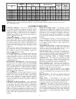
Page 1: ...t Surface Igniter S SmartEvap technology helps control humidity levels in the home when used with a compatible humidity control system S FanOn Plus technology allows control of continuous fan speed fr...

Page 2: ...and continues Bryant s tradition of technology leadership and innovation in providing a reliable and durable product Full Featured Variable Speed Motors Our variable speed ECM Electronically Commutat...

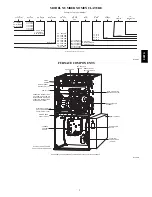
Page 3: ...U 120 120 000 BTU 140 140 000 BTU Not all familes have these models 0 90 AFUE 2 92 AFUE 3 93 AFUE 5 95 AFUE 6 96 AFUE 7 97 AFUE Example of a Model Number A14367 FURNACE COMPONENTS RATING PLATE NOT SHO...

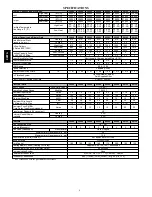
Page 4: ...peed Selections Variable PWM Blower Wheel Dia x Width in 11 x 7 11 x 8 11 x 7 11 x 8 11 x 8 11 x 10 11 x 10 11 x 11 Air Filtration System Optional Media Cabinet Field Supplied Filter Filter Used for C...

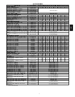
Page 5: ...as Orifice Kit 46 Nat Gas LH32DB208 D D D D D D D D Gas Orifice Kit 47 Nat Gas LH32DB078 D D D D D D D D Gas Orifice Kit 48 Nat Gas LH32DB076 D D D D D D D D Gas Orifice Kit 54 LP LH32DB203 D D D D D...

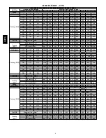
Page 6: ...ON OFF 770 725 685 640 600 560 515 480 See note 4 OFF ON ON 945 910 875 835 800 770 735 695 665 635 ON OFF OFF 1140 1105 1075 1040 1005 970 930 885 835 790 ON OFF ON 1250 1210 1165 1115 1065 1015 965...

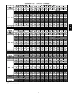
Page 7: ...770 720 660 620 585 ON OFF OFF 1175 1140 1090 1060 1025 980 940 905 855 815 ON OFF ON 1325 1280 1245 1210 1180 1140 1105 1070 1025 990 ON ON OFF 1545 1515 1480 1445 1410 1380 1350 1315 1245 1175 ON O...

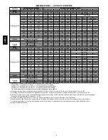
Page 8: ...1890 1750 1645 1550 Clg SW2 Maximum Clg Airflow 2 note 8 2375 2300 2205 2115 2010 1890 1750 1645 1550 Heating SW1 High Heat Airflow 3 note 8 2375 2300 2205 2115 2010 1890 1750 1645 1550 Low Heat Airfl...

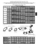
Page 9: ...2 NA NA 60 000 23 7 0 119 36 3 210 64 0 235 71 6 NA 80 000 15 4 6 59 18 0 155 47 2 210 64 0 232 70 7 100 000 NA 19 5 8 98 29 9 211 64 3 236 71 9 120 000 NA NA 8 2 4 86 26 2 224 68 3 140 000 4 NA NA NA...

Page 10: ...ent Vent Length TEVL 112 ft Add all of the above lines Maximum Equivalent Vent Length MEVL 127 ft For 2 pipe from Table 1 Is TEVL less than MEVL YES Therefore 2 pipe may be used Example 2 A direct ven...

Page 11: ...9 8 63 19 2 8001 to 9000 2438 to 2743 40 000 10 3 0 121 36 9 130 39 6 NA NA 60 000 7 2 1 82 25 0 152 46 3 168 51 2 NA 80 000 NA 35 10 7 111 33 8 148 45 1 156 47 5 100 000 NA NA 67 20 4 157 47 9 170 51...

Page 12: ...44 8 0 20 Ft 20 0 32 0 30 0 22 0 11 0 20 0 70 0 104 0 87 0 67 0 20 0 70 0 124 0 104 0 82 0 M 6 1 9 8 9 1 6 7 3 4 6 1 21 3 31 7 26 5 20 4 6 1 21 3 37 8 31 7 25 0 20 30 Ft 20 0 17 0 14 0 6 0 0 0 20 0 7...

Page 13: ...PLY AIR A10490 MINIMUM CLEARANCES TO COMBUSTIBLE MATERIALS POSITION CLEARANCE Rear 0 0 mm Front Combustion air openings in furnace and in structure 1 in 25 mm Required for service 24 in 610 mm All Sid...

Page 14: ...5 8 600 2 24 1 2 622 Furnace with or without Cased Coil Assembly or Coil Box 22 1 8 562 19 483 23 3 4 603 20 5 8 600 1 The plenum should be constructed 1 4 in 6 mm smaller in width and depth than the...

Page 15: ...FIELD SUPPLIED DISCONNECT AUXILIARY J BOX 24 V TERMINAL BLOCK THREE WIRE HEATING ONLY FIVE WIRE NOTE 1 NOTE 2 FIELD SUPPLIED DISCONNECT CONDENSING UNIT TWO WIRE FURNACE C O N T R O L R G COM W C R G Y...

Page 16: ...IMENSIONS IN INCH MM 22 2 7 8 7 8 22 2 POWER CONN AIR FLOW SEE NOTE 3 NOTES 1 Doors may vary by model 2 Minimum return air openings at furnace based on metal duct If flex duct is used see flex duct ma...

Page 17: ...Casing Casing shall be of 030 in thickness minimum pre painted steel Draft Inducer Motor Draft inducer motor shall be two speed PSC design Primary Heat Exchangers Primary heat exchangers shall be 3 P...

Page 18: ...e or change at any time specifications or designs without notice and without incurring obligations E2014 Bryant Heating Cooling Systems D 7310 W Morris St D Indianapolis IN 46231 Edition Date 09 14 Re...

Reviews: