


47
7. Apply cement to the end of the pipe and to the inside of the
plastic vent adapter.
8. Slide the adapter over the vent pipe and align the screw
holes in the adapter with the dimples in the furnace casing.
9. Pilot drill 1/8--in. screw holes for the adapter in the casing
and secure the adapter to the furnace with sheet metal
screws.
10. Loosen the clamps on the rubber vent coupling.
11. Slide the end of the coupling with notches in it over the
standoffs in the vent pipe adapter.
12. Tighten the clamp of the coupling over the vent pipe
adapter. Torque the lower clamp around the vent pipe
adapter to 15 lb--in.
13. Pilot drill a 1/8--in. hole in the combustion air pipe adapter.
14. Complete the vent and combustion air pipe as shown in
“Install the Vent and Combustion Air Pipe.”
FOR POLYPROPYLENE VENTING SYSTEMS
When using polypropylene venting systems, all venting
materials used, including the vent terminations, must be from
the same manufacturer.
NOTICE
Installing the Vent Termination
Roof Terminations
A roof termination of any type will require a 4-in. (102 mm)
flashing for a 2 in. (50 mm ND) concentric vent or a 5--in. diameter
(127 mm) flashing for a 3-in. (80 mm ND) concentric vent kit. For
two-pipe or single pipe vent systems, a flashing for each pipe of the
required diameter will be necessary.
It is recommended that the flashing be installed by a roofer or
competent professional prior to installing the concentric vent. The
terminations can be installed on a flat or pitched roof.
Concentric Vent
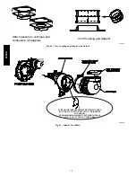
Single or multiple concentric vent must be installed as shown in
Fig. 53. Maintain the required separation distance between vents
or pairs of vents as shown in Fig. 53 and all clearance shown in
Fig. 51.
NOTE
: Follow the instructions of the vent terminal manufacturer.
These instructions are provided as a reference, only.
Cut one 4--in. (102 mm) diameter hole for 2--in. (50 mm ND) kit,
or one 5--in. (127 mm) diameter hole for 3--in. (80 mm ND) kit in
the desired location.
Loosely assemble concentric vent/combustion air termination
components together using instructions in kit.
Slide assembled kit with rain shield
REMOVED
through hole in
wall or roof flashing.
NOTE
: Do not allow insulation or other materials to accumulate
inside of pipe assembly when installing it through hole.
Disassemble loose pipe fittings. Clean and cement using same
procedures as used for system piping.
DO NOT CEMENT
POLYPROPYLENE FITTINGS.
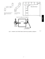
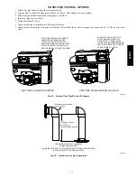
Two--Pipe and Single--Pipe Terminations
Single and two pipe vent must be installed as shown in Fig. 53 and
54. Maintain the required separation distance between vents or
pairs of vents as shown in Fig. 53 and 54 and all clearance shown
in Fig. 51 and 52 .
RECOMMENDED SUPPORT FOR VENT
TERMINATIONS
It is recommended that rooftop vent terminations in excess of
36 inches (1 M) in vertical length be supported by
EITHER
the Direct Vent Termination Kit shown in Table 12 or by
field--supplied brackets or supports fastened to the structure.
NOTICE
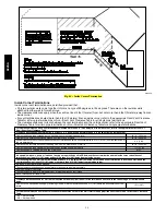
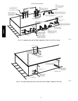
Cut the required number of holes in the roof or sidewall for vent
and (when used) combustion air pipes. Sidewall holes for two-pipe
vent terminations should be side-by-side, allowing space between
the pipes for the elbows to fit on the pipes.
Holes in the roof for direct--vent two--pipe terminations should be
spaced no more than 18 in. (457 mm) apart to help avoid vent gas
recirculation into combustion air intake.
Termination elbows will be installed after the vent and (if used)
combustion air pipe is installed.
Sidewall Terminations
Concentric Vent
NOTE
: Follow the instructions of the vent terminal manufacturer.
These instructions are provided as a reference only.
Determine an appropriate location for termination kit using the
guidelines provided in section “Locating The Vent Termination” in
this instruction.
1. Cut one 4--in. diameter hole for 2--in. kit, or one 5--in. diam-
eter hole for 3--in. kit.
2. Loosely assemble concentric vent/combustion air termina-
tion components together using instructions in kit.
3. Slide assembled kit with rain shield REMOVED through
hole.
NOTE
: Do not allow insulation or other materials to accumulate
inside of pipe assembly when installing it through hole.
4. Locate assembly through sidewall with rain shield posi-
tioned no more than 1--in. (25 mm) from wall as shown in
Fig. 53.
5. Disassemble loose pipe fittings. Clean and cement using
same procedures as used for system piping.
DO NOT CE-
MENT POLYPROPYLENE FITTINGS.
2-Pipe and 1-Pipe Vent Termination
NOTE
: Follow the instructions of the vent terminal manufacturer.
These instructions are provided as a reference, only.
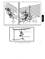
RECOMMENDED SUPPORT FOR VENT
TERMINATIONS
It is recommended that sidewall vent terminations in excess of
24 inches (0.6 M) in vertical length be supported by
EITHER
the Direct Vent Termination Kit shown in Table 12 or by
field--supplied brackets or supports fastened to the structure.
NOTICE
Determine an appropriate location for termination kit using the
guidelines provided in section “Locating The Vent Termination” in
this instruction.
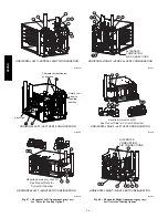
1. Cut two holes, one for each pipe, of appropriate size for
pipe size being used.
2. Loosely install elbow in bracket (if used) and place assem-
bly on combustion--air pipe.
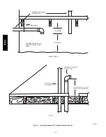
3. Install bracket as shown in Fig. 53 and 55.
NOTE
: For applications using vent pipe option indicated by
dashed lines in Fig. 53 and 54, rotate vent elbow 90
_
from
position.
922SA


