16
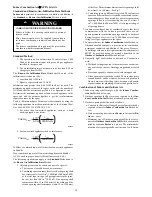
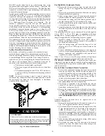
4. Install the drain trap grommet in the casing if required for
direct--vent applications. If necessary, remove the trap,
install the grommet and re-install the trap.
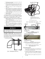
5. Remove the pre-formed rubber drain elbow, and two spring
clamps from the loose parts bag.
6. Connect the full or modified elbow and/or grommet to the
outlet of the condensate trap with one spring clamp. Avoid
misalignment of the drain pipe which may cause kinks in
the elbow or grommet.
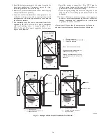
7. The remaining drain line can be constructed from field--
supplied 1/2--in. CPVC or 3/4--in. PVC pipe, in compliance
with local building codes. A factory--supplied 1/2--in.
CPVC to 3/4--in. PVC adapter is supplied in the loose parts
bag for use as required.
8. Install the adapter or connect the 1/2--in. CPVC pipe by
sliding a spring clamp over the open end of the elbow or
grommet on the outside the furnace casing.
9. Open the spring clamp and insert the long end of the
adapter or the 1/2--in. CPVC pipe into the outlet stub on the
drain tube.
10. Connect additional condensate piping to a code--approved
drain, or to a condensate pump approved for use with acidic
furnace condensate and compatible with mineral and
vegetable oils, such as canola oil.
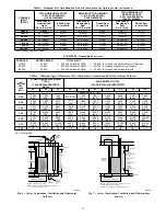
Allow at least 1/4-in. per foot (20 mm per meter) of slope down
and away from the furnace in horizontal sections of drain line.
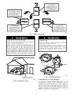
+
+
+
Condensing
Furnace
-
-
- -
-
Evaporator Coil
+ +
+
< +
< +
< +
+
Blower
-
+
= Positive pressure
< +
= Pressure lower than areas with
+
−
= Negative pressure
Blower creates positive pressure.
Positive pressure extends into coil
condensate drain (no trap).
Furnace condensate does not flow
consistently when drain is at positive
pressure.
+
DIRECT
ION
OF
AI
RF
L
O
W
+
+
+
+
+
+
+
+
+
+
Condensing
Furnace
-
-
- -
-
Evaporator Coil
+
+
+
< +
< +
< +
+
Blower
-
3/4” PVC
1/2
3/4
1/2” CPVC or larger*
+
= Positive pressure
< +
= Pressure lower than areas with
+
−
= Negative pressure
+
3/4” PVC
DIRECT
ION
OF
AI
RF
L
O
W
+
+
+
+
1/2
3/4
3/4
3/4
Open
standpipe
+
+
3/4
+
+
+
+
Condensing
Furnace
-
-
- -
-
Evaporator Coil
+
+
+
< +
< +
< +
+
Blower
-
3/4” PVC
3/4
1/2” CPVC or larger*
+
= Positive pressure
< +
= Pressure lower than areas with
+
−
= Negative pressure
+
3/4” PVC
DIRECT
ION
OF
AI
RF
L
O
W
+
+
+
+
3/4
3/4
3/4
3/4
3/4
+
+
+
+
+
+
+
+
+
+
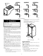
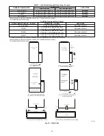
A14532
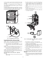
Fig. 17 -- Example of Field Drain Attachment (Not Allowed)

