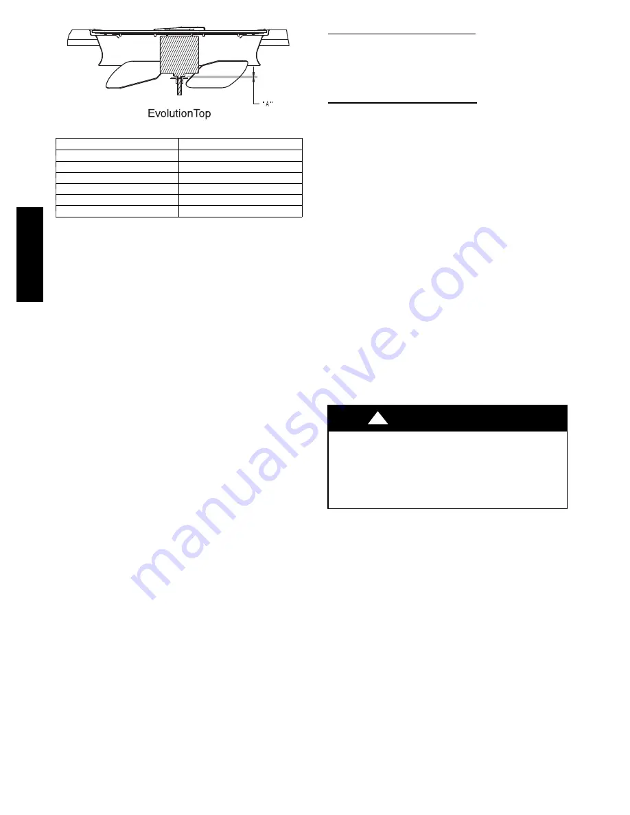
34
A06132
UNIT SIZE
“A” DIM. IN. (MM)
24
1 (26)
30
1 (26)
36
1 (26)
42
1 (26)
48
11/32 (9)
60
9/16 (14)
Fig. 28 -- Outdoor Fan Blade Clearance
Electrical Controls and Wiring
Inspect and check the electrical controls and wiring annually. Be
sure to turn off the electrical power to the unit.
Remove access panel to locate all the electrical controls and wiring.
Check all electrical connections for tightness. Tighten all screw
connections. If any smoky or burned connections are noticed,
disassemble the connection, clean all the parts, re--strip the wire
end and reassemble the connection properly and securely.
After inspecting the electrical controls and wiring, replace all the
panels. Start the unit, and observe at least one complete cooling
cycle to ensure proper operation. If discrepancies are observed in
operating cycle, or if a suspected malfunction has occurred, check
each
electrical
component
with
the
proper
electrical
instrumentation. Refer to the unit wiring label when making these
checks.
Refrigerant Circuit
Inspect all refrigerant tubing connections and the unit base for oil
accumulation annually. Detecting oil generally indicates a
refrigerant leak.
If oil is detected or if low performance is suspected, leak test all
refrigerant tubing using an electronic leak detector, or liquid--soap
solution. If a refrigerant leak is detected, refer to Check for
Refrigerant Leaks section.
If no refrigerant leaks are found and low performance is suspected,
refer to Checking and Adjusting Refrigerant Charge section.
Indoor Airflow
The heating and/or cooling airflow does not require checking
unless improper performance is suspected. If a problem exists, be
sure that all supply-- and return--air grilles are open and free from
obstructions, and that the air filter is clean.
Metering Devices--TXV & AccuRater
®
Piston
This unit uses 2 types of metering devices. The outdoor metering
device is a fixed orifice and is contained in the brass--hex body in
the liquid line feeding the outdoor coils. The indoor metering
device is a TXV--type device. No maintenance should be required.
Pressure Switches -- Refrigerant Circuit
Pressure switches are protective devices integrated into the control
circuit (low voltage). They shut off compressor if abnormally high
or low pressures are present in the refrigeration circuit. These
pressure switches are specifically designed to operate with Puron
(R--410A) systems. R--22 pressure switches must not be used as
replacements for the Puron (R--410A) system.
Loss--of--Charge (Low Pressure) Switch
This switch is located on the liquid line and protects against low
suction pressures caused by such events as loss of charge, low
airflow across indoor coil, dirty filters, etc. It opens if the system
pressure drops to about 20 psig. If system pressure is above this,
switch should be closed.
High--Pressure Switches (HPS & HPS2)
The high--pressure switches are located on the discharge line and
protects against excessive condenser coil pressure. HPS opens at
670 psig shutting down the compressor, while HPS2 opens at 565
psig, limiting the compressor to low--stage operation only.
High pressure may be caused by a dirty outdoor coil, failed fan
motor, or outdoor air recirculation.
To check switches:
1. Turn off all power to unit.
2. Disconnect leads on switch.
3. Apply ohm meter leads across switch. You should have
continuity on a good switch.
NOTE
:
Because these switches are attached to refrigeration
system under pressure, it is not advisable to remove this device for
troubleshooting unless you are reasonably certain that a problem
exists. If switch must be removed, remove and recover all system
charge so that pressure gauges read 0 psi. Never open system
without breaking vacuum with dry nitrogen.
Copeland Scroll Compressor (Puron Refrigerant)
The compressor used in this product is specifically designed to
operate with Puron (R--410A) refrigerant and cannot be
interchanged.
The compressor is an electrical, as well as mechanical, device.
Exercise extreme caution when working near compressors. Power
should be shut off, if possible, for most troubleshooting techniques.
Refrigerants present additional safety hazards.
EXPLOSION, FIRE HAZARD
Failure to follow this warning could result in personal
injury or death and/or property damage.
Wear safety glasses and gloves when handling refrigerants.
Keep torches and other ignition sources away from
refrigerants and oils.
!
WARNING
The scroll compressor pumps refrigerant throughout the system by
the interaction of a stationary and an orbiting scroll. The scroll
compressor has no dynamic suction or discharge valves, and it is
more tolerant of stresses caused by debris, liquid slugging, and
flooded starts. The compressor is equipped with a noise reducing
shutdown device and an internal pressure--relief port. The noise
reducing device prevents the scroll from turning backwards and
replaces the need for a cycle protector. The pressure--relief port is a
safety device, designed to protect against extreme high pressure.
The relief port has an operating range between 550 and 625 psig
differential pressure.
Refrigerant System
This step covers the refrigerant system of the 677D----A, including
the compressor oil needed, servicing systems on roofs containing
synthetic materials, the filter drier, and refrigerant charging.
677D
--
--
A


