—7—
F. Make Piping Sweat Connections
Remove plastic caps from liquid and suction service valves.
Use refrigerant grade tubing.
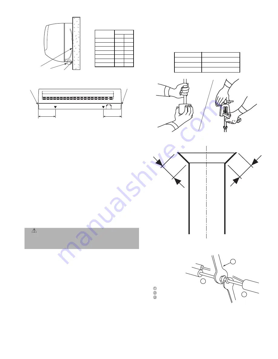
Position tube end downward and cut the tube to the
requested length. Remove the burrs with a reamer. See
Fig. 12.
NOTE
: Oil in the compressor is extremely susceptible to
moisture absorption. Keep ends of tubing sealed during
installation.
Remove flare nuts from the unit connections and place them
on the tube end. Flare the tube with the flaring tool. The
flare end must not have any burrs or imperfections. The
length of the flared walls must be uniform. See Fig. 13.
Lubricate the tube end and thread of the flare fitting with
antifreeze oil. Tighten the fitting several turns, then tighten
it fully with two wrenches by applying the tightening torque
indicated in Table 4 and Fig. 14.
G. Air Purging And Leak Test
Only use a vacuum pump to purge air from the piping. Refer
to Fig. 15.
IMPORTANT:
Do not use the system compressor as a vacuum
pump.
IMPORTANT:
Do not use the unit refrigerant gas to purge
the connecting pipes.
Remove the caps from the valves.
Create a vacuum with a
vacuum pump connected to the service connection
of the suc-
tion shut-off valves completely shut until a 50 Pa vacuum
has been reached.
Open the mixed phase valve for 3 seconds, then quickly shut
it to check for possible leaks.
Replace caps and check for leaks using a leak detector spe-
cific for R-410A refrigerant.
After the leak test, fully open the three-way valves.
Table 4 — Tightening Torque
CAUTION:
Insufficient tightening torque will
cause gas leaks. Overtightening the fittings will dam-
age the tube flaring and cause gas leaks. Equipment
damage and personal injury may result.
VALVE SIZE
FLARE NUT (in.-lb)
3
/
8
in.
372
5
/
8
in.
487
3
/
4
in.
885
A
Wall
Hanging
Bracket
Hook
Hole
Retainer
Clip
Retainer
Clip
B
UNIT SIZE
DIMENSION
A
B
619ENF01824
13.4
10.6
619ENF030
12.2
12.2
619ENF036
12.2
12.2
619ENQ018
13.4
10.6
619ENQ024
13.4
10.6
619ENQ030
12.2
12.2
619ENQ036
12.2
12.2
Fig. 11 — Wall Hanging Details
Fig. 12 — Removing Burrs
L
L
Fig. 13 — Flared Walls are Equal
Fig. 14 — Tightening Connections
Adjustable wrench or torque wrench
Outdoor end
Indoor end
3
1
2
Summary of Contents for 619ENF
Page 9: ... 9 Fig 16 619ENF01824 Matched with 538ENF Typical Wiring Schematic ...
Page 10: ... 10 Fig 17 619ENQ018 024 Matched with 538QNF Typical Wiring Schematic ...
Page 11: ... 11 Fig 18 619ENF030 036 Matched with 538ENF Typical Wiring Schematic ...
Page 12: ... 12 Fig 19 619ENQ030 036 Matched with 538QNF Typical Wiring Schematic ...
Page 16: ...Copyright 2006 Bryant Heating Cooling Systems Printed in U S A CATALOG NO 02 619E0001 SI ...


