background image

—2—

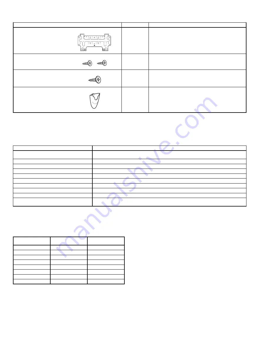
Table 1A — Installation Materials — Included In Shipment

*619ENF01824, 619ENQ018,024: 5

619ENF,ENQ030,036: 14

Table 1B — Installation Materials — Field-Supplied

LEGEND

Table 2 — Matching Indoor Units to Outdoor Units

See Fig. 2 for unit dimensions. Allow sufficient space for air-

flow clearance, wiring, refrigerant piping, and servicing

units. See Fig. 3.
Avoid mounting the unit in areas that are:
• exposed to direct sunlight

• too close to heat sources

• too close to humid conditions

• located in an area with oily ambient conditions.

DESCRIPTION

QTY

USAGE

Wall Hanging Bracket

1

For indoor unit installation.

Screws, 4xL10

2

For affixing unit and hanging bracket.

Screws, 5xL25

5/14*

For wall hanging bracket installation.
For wireless remote control mounting bracket installation.

Wireless Remote Control 
Mounting Bracket

1

For wireless remote control installation.

NAME

SPECIFICATIONS

Connection Pipe (nominal capacity)

Liquid line: 

3

/

8

 in. (619ENF,ENQ018-036)

Mixed Phase line: 

5

/

8

 in. (619ENF01824 and 619ENQ018,024), 

3

/

4

 in. (619ENF,ENQ030,036)

Wall Sleeve

Wall Cap

Finishing Tape

PVC Film

Fastening Tape

Pipe Insulation

Drain Hose

5

/

8

 in. (619ENF01824 and 619ENQ018,024) 

3

/

4

 in. (619ENF,ENQ030,036)

Sealer Putty

Power Supply Cable

AWG 14 or higher

Electrical Connecting Cable Between

Indoor and Outdoor Unit

Cable Type: AWG 14 synthetic rubber insulation with Neoprene coating, according to NEC codes.

AWG —

American Wire Gage

NEC —

National Electrical Code

OUTDOOR UNIT

COOLING ONLY OR 

HEAT PUMP

INDOOR UNIT

538ENF018

Cooling Only

619ENF01824

538ENF024

Cooling Only

619ENF01824

538ENF030

Cooling Only

619ENF030

538ENF036

Cooling Only

619ENF036

538QNF018

Heat Pump

619ENQ018

538QNF024

Heat Pump

619ENQ024

538QNF030

Heat Pump

619ENQ030

538QNF036

Heat Pump

619ENQ036

Summary of Contents for 619ENF

Page 1: ...EC for special installation requirements GENERAL These instructions cover the installation start up and service of cooling only and heat pump duct free systems INSTALLATION I STEP 1 COMPLETE PRE INSTALLATION CHECKS A Unpack Units See Fig 1 Move the unit to final location Remove unit from carton being careful not to damage service valves and grilles See Table 1A for installation materials included ...

Page 2: ...eless Remote Control Mounting Bracket 1 For wireless remote control installation NAME SPECIFICATIONS Connection Pipe nominal capacity Liquid line 3 8 in 619ENF ENQ018 036 Mixed Phase line 5 8 in 619ENF01824 and 619ENQ018 024 3 4 in 619ENF ENQ030 036 Wall Sleeve Wall Cap Finishing Tape PVC Film Fastening Tape Pipe Insulation Drain Hose 5 8 in 619ENF01824 and 619ENQ018 024 3 4 in 619ENF ENQ030 036 S...

Page 3: ... 619ENF ENQ 16 16 16 20 18 18 18 18 Circuits 5 5 9 9 FILTERS Quantity Size in 2 12 5 x 16 1 2 12 5 x 16 1 3 17 3 x 16 1 3 17 3 x 16 1 AIR SWEEP Horizontal Manual Manual Automatic Automatic Vertical Automatic Automatic Automatic Automatic OPERATING LIMITS Heating Min Max 81 F db Cooling Min Max 59 F wb 70 F db 74 F wb 90 F db CONTROLS Integrated Microprocessor Remote Controller Options Wireless CRC...

Page 4: ...in min min 4 in 4 in 80 in 8 in Fig 2 Unit Dimensions 619ENF01824 619ENQ018 024 DIMENSIONS in 619ENF ENQ 030 036 DIMENSIONS in A 42 5 57 5 B 11 6 13 4 C 7 9 9 5 619ENF ENQ 619ENF ENQ UNITS Fig 3 Unit Clearances ...

Page 5: ...P 3 COMPLETE REFRIGERANT PIPING CONNECTIONS When running the piping for indoor units the piping can be con nected as rear piping or side or bottom piping Refer to Fig 4 A Rear Piping Route the piping behind the indoor unit so that the piping is concealed by the unit For rear piping installation drill a 21 2 in diameter hole in the wall at point A or B in Fig 6 Drill the hole at a slope so that the...

Page 6: ... line sizes Do not use less than 10 ft of interconnecting tubing If either refrigerant tubing or indoor coil is exposed to the atmosphere the system must be evacuated following good refrigeration practices Run refrigerant tubes as directly as possible avoiding unnecessary turns and bends Suspend refrigerant tubes so they do not damage insulation on vapor tube and do not transmit vibration to struc...

Page 7: ...Do not use the unit refrigerant gas to purge the connecting pipes Remove the caps from the valves Create a vacuum with a vacuum pump connected to the service connection of the suc tion shut off valves completely shut until a 50 Pa vacuum has been reached Open the mixed phase valve for 3 seconds then quickly shut it to check for possible leaks Replace caps and check for leaks using a leak detector ...

Page 8: ...e possibility of personal injury if an electrical fault should occur This ground may consist of electrical wire connected to unit ground lug in control compart ment or conduit approved for electrical ground when installed in accordance with NEC and local electrical codes Failure to follow this warning could result in the installer being liable for the personal injury of others CAUTION Unit failure...

Page 9: ... 9 Fig 16 619ENF01824 Matched with 538ENF Typical Wiring Schematic ...

Page 10: ... 10 Fig 17 619ENQ018 024 Matched with 538QNF Typical Wiring Schematic ...

Page 11: ... 11 Fig 18 619ENF030 036 Matched with 538ENF Typical Wiring Schematic ...

Page 12: ... 12 Fig 19 619ENQ030 036 Matched with 538QNF Typical Wiring Schematic ...

Page 13: ...re being installed in the same room working independently two remote controls need to be con figured for proper operation A Unit Configuration Turn the unit off by pressing the Press and hold the and buttons of the remote control for more than 5 seconds The display will be cleared and the time segments will display the first configuration item rAdr remote address and the temperature segments will ...

Page 14: ...t in operation the green LED on the indoor unit flashes at intervals of 0 5 sec onds The fault code is deduced from the number of times the green LED flashes blocking unit operation Between one flash cycle and the next one a pause of 3 seconds elapses Table 6 Green LED Indoor Unit Fault WARNING Before performing recommended maintenance be sure unit main power switch is turned off Failure to do so ...

Page 15: ...on Indoor temperature setting too low or too high Check temperature setting Outdoor unit fan faulty Replace outdoor fan Air or other noncondensable gasses in the circuit Drain refrigerant evacuate and recharge CAUTION Do not vent refrigerant to the atmosphere use refrigerant recovery equipment Obstructions at air intake or dirty indoor unit filters Remove obstruction and or clean filter Frequent I...

Page 16: ...Copyright 2006 Bryant Heating Cooling Systems Printed in U S A CATALOG NO 02 619E0001 SI ...

Reviews: