Bryant 598A Series D Installation And Start-Up Instructions Manual Download Page 4

IMPORTANT:

Check factory wiring and wire connections to

ensure terminations are secured properly. Check wire routing to
ensure wires are not in contact with tubing, sheet metal, etc.

VIII.

INSTALL ELECTRICAL ACCESSORIES

A.

General

Refer to the individual instructions packaged with kits or acces-
sories when installing.

CAUTION:

Low-ambient kits are not available for

2-speed units. Do not attempt to operate below 55°F or
modify control system for low-ambient operation. Com-
pressor damage may occur.

Available electrical accessories include latent capacity control. See
Table 2 and Fig. 7 for typical accessory wiring diagrams.

B.

Latent Capacity Control (LCC)

The purpose of an LCC is to provide a dehumidification mode to
assure a 75 percent or less system sensible heat ratio. If indoor unit
installed contains an ICM blower (such as an FK4C fan coil or a
333(B,J)AV or 355MAV gas furnace), no LCC is required. Indoor
products with ICM blowers have enough CFM range to provide
proper airflow for low-speed cooling. If indoor unit installed has a
standard PSC blower motor, the low-speed airflow available is too
great to assure 75 percent or less system sensible heat ratio. The
LCC for standard blower products consists of a standard humidis-
tat which opens contacts on humidity rise and a pilot duty relay
with 24-v coil.

NOTE:

If an LCC is desired, low-speed airflow must be main-

tained so that a minimum of 300 CFM/ton can be supplied during
high-speed LCC operation.

LCC OPERATION FOR TYPICAL PSC FAN COILS

The standard blower operation for systems with typical PSC fan
coils is covered in Fig. 7A, B, and D. The blower runs in high
speed regardless if compressor operation is high or low speed.
When the LCC is wired according to Fig. 7A, B, or D and humidity
rises, the humidistat contacts open and de-energize the relay. If
relay is de-energized, the system operates on high-speed compres-
sor and high-speed airflow until humidistat closes. Fig. 7C shows
the wiring with a Bryant Thermidistat which controls temperature
and humidity level without the need for an additional humidistat
and relay.

LCC OPERATION FOR TYPICAL PSC FURNACES

The standard blower operation of systems with typical PSC
furnaces is covered in Fig. 7J, K, M, N, P, or R. The blower runs
in high or low speed in conjunction with compressor high- or
low-speed operation. When the LCC is wired according to Fig. 7K,
M, N, P, or R and humidity rises, the humidistat contacts open and
de-energize the relay. If relay is de-energized, the system operates
on high-speed compressor and low-speed airflow until humidistat
closes. Fig. 7L and 7Q shows the wiring with a Bryant Thermi-
distat which controls temperature and humidity level without the
need for an additional humidistat and relay.

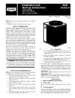
Fig. 6—Line Power Connections

A91306

CONTACTOR

DISCONNECT
PER N. E. C. AND/ OR
LOCAL CODES

FIELD POWER

WIRING

FIELD GROUND

WIRING

GROUND
LUG

TABLE 2—WIRING DIAGRAM REFERENCE

INDOOR PRODUCT

THERMOSTAT

CONTROLS

DIAGRAM LETTER

IN FIG. 7

Standard Fan Coil

Bryant Programmable (Model 2S)

Latent Capacity

A

Bryant Non-Programmable (Model 2S)

Latent Capacity

B

Bryant Thermidistat™ Control

Humidifier and Outdoor Sensor

C

Other Brand Models

Latent Capacity

D

FK4C Fan Coil

Bryant Programmable (Model 2S)

E

Bryant Non-Programmable (Model 2S)

F

Bryant Thermidistat™ Control

Humidifier and Outdoor Sensor

G

Other Brand Models

H

Single-Stage Furnace

Bryant Programmable (Model 2S)

Latent Capacity

J

Bryant Non-Programmable (Model 2S)

Latent Capacity

K

Bryant Thermidistat™ Control

Humidifier and Outdoor Sensor

L

Other Brand Models

Latent Capacity

M

Two-Stage Furnace with PSC Blower Motor

Bryant Programmable (Model 2S)

Latent Capacity

N

Bryant Non-Programmable (Model 2S)

Latent Capacity

P

Bryant Thermidistat™ Control

Humidifier and Outdoor Sensor

Q

Other Brand Models

Latent Capacity

R

Two-Stage Furnace with ICM Blower Motor

Bryant Programmable (Model 2S)

S

Bryant Non-Programmable (Model 2S)

T

Other Brand Models

U

Variable-Speed 80% Non-Condensing Furnace

Bryant Thermidistat™ Control

Humidifier and Outdoor Sensor

V

Variable-Speed Condensing Furnace

Bryant Thermidistat™ Control

Humidifier and Outdoor Sensor

W

—4—

Summary of Contents for 598A Series D

Page 1: ...om improper installation of equipment 1 Locate unit away from windows patios decks etc where unit operation sound may disturb customer 2 Ensure that vapor and liquid tube diameters are appropriate to capacity of unit 3 Run refrigerant tubes as directly as possible by avoiding unnecessary turns and bends 4 Leave some slack between structure and unit to absorb vibration 5 When passing refrigerant tu...

Page 2: ...ient in cooling mode is 125 F V REMOVE INDOOR CHECK FLO RATER PISTON AND REPLACE WITH TXV CAUTION For proper unit operation and reliability the outdoor unit must be installed with the factory supplied balance port hard shutoff TXV Do not install with evaporator coils having capillary tube metering devices After removing existing Check Flo Rater from indoor coil install factory supplied thermostati...

Page 3: ...oved Be sure field wiring complies with local and national fire safety and electrical codes and voltage to system is within limits shown on unit rating plate Contact local power company for correction of improper voltage See unit rating plate for recommended circuit protection device NOTE Operation of unit on improper line voltage constitutes abuse and could affect unit reliability See unit rating...

Page 4: ... a Bryant Thermidistat which controls temperature and humidity level without the need for an additional humidistat and relay LCC OPERATION FOR TYPICAL PSC FURNACES The standard blower operation of systems with typical PSC furnaces is covered in Fig 7J K M N P or R The blower runs in high or low speed in conjunction with compressor high or low speed operation When the LCC is wired according to Fig ...

Page 5: ...AC COMM N A OUTDOOR SENSOR CONNECTION C B S1 S2 C Y2 C BRYANT PROGRAMMABLE THERMOSTAT MODEL 2S TYPICAL FAN COIL TWO SPEED AIR CONDITIONER See notes 6 and 8 W2 Y E R W3 Y1 L H R1 D A97458 R C C Y1 TYPICAL FAN COIL TWO SPEED AIR CONDITIONER See note 8 Y G W2 R Y2 E W3 L H R1 24 VAC HOT 24 VAC COM HEAT STAGE 1 COOL STAGE 2 FAN R C G W Y2 Y1 OTHER BRAND TWO SPEED THERMOSTATS COOL STAGE 1 B A97453 24 V...

Page 6: ...PROGRAMMABLE THERMOSTAT MODEL 2S FK4C FAN COIL J1 JUMPER REMOVE J2 JUMPER FOR HEAT STAGING TWO SPEED AIR CONDITIONER See notes 6 8 and 19 DH Y1 Y1 W W1 O W2 Y1 W2 W1 Y Y2 Y2 Y Y2 O W2 H A97459 R Y2 R Y2 C C C R L Y1 OTHER BRAND TWO SPEED THERMOSTATS FK4C FAN COIL TWO SPEED AIR CONDITIONER J1 JUMPER REMOVE J2 JUMPER FOR HEAT STAGING G G Y Y2 DH W W1 Y1 W2 Y1 O W2 24 VAC HOT 24 VAC COM FAN COOL STAG...

Page 7: ... W2 G 24 VAC COMM N A OUTDOOR SENSOR CONNECTION C B S1 S2 C Y2 C BRYANT PROGRAMMABLE THERMOSTAT MODEL 2S SINGLE STAGE FURNACE TWO SPEED AIR CONDITIONER See note 6 W R Y1 R G L Y H R1 M A97455 24 VAC HOT 24 VAC COM HEAT STAGE 1 COOL STAGE 2 FAN R C G W Y2 R C Y1 C OTHER BRAND TWO SPEED THERMOSTATS SINGLE STAGE FURNACE TWO SPEED AIR CONDITIONER G W R Y Y2 L Y1 H R1 COOL STAGE 1 K A97450 24 VAC HOT 2...

Page 8: ... 1 FAN HEAT STAGE 1 COOL STAGE 2 HEAT STAGE 2 24 VAC HOT R W W1 Y Y2 O W2 Y1 W2 24 VAC COMM N A OUTDOOR SENSOR CONNECTION C B S1 S2 BRYANT PROGRAMMABLE THERMOSTAT MODEL 2S G H R1 A97457 24 VAC HOT 24 VAC COM HEAT STAGE 1 COOL STAGE 2 FAN R C G W Y2 R C Y1 C OTHER BRAND TWO SPEED THERMOSTATS TWO STAGE FURNACE WITH PSC BLOWER MOTOR TWO SPEED AIR CONDITIONER See notes 7 and 17 G R Y2 L W W1 Y Y2 W2 Y...

Page 9: ...W1 Y Y2 O W2 Y1 W2 G 24 VAC COMM N A OUTDOOR SENSOR CONNECTION C B S1 S2 C Y2 C BRYANT PROGRAMMABLE THERMOSTAT MODEL 2S TWO STAGE VARIABLE SPEED FURNACE WITH ICM BLOWER MOTOR TWO SPEED AIR CONDITIONER See notes 6 7 16 and 17 R Y1 R G L W W1 Y Y2 W2 Y1 24 VAC HOT 24 VAC COMM HEAT STAGE 1 COOL STAGE 2 FAN R C G W W1 Y Y2 R C HEAT STAGE 2 COOL STAGE 1 N A OUTDOOR SENSOR CONNECTION Y1 B S1 S2 C BRYANT...

Page 10: ... FAN 24 VAC HOT 24 VAC COM DEHUMIDIFY HUMIDIFY N A OUTDOOR SENSOR CONNECTIONS Y Y2 HUMIDIFIER 24 VAC OUTDOOR SENSOR See notes 11 12 13 15 16 and 17 O W2 W W1 Y1 W2 G R BRYANT THERMIDISTAT CONTROL VARIABLE SPEED CONDENSING FURNACE TWO SPEED AIR CONDITIONER W W1 G Y Y2 C Y2 R Y1 C DHUM HUM B S1 S2 W2 R C HEAT STAGE 1 COOL STAGE 1 COOL STAGE 2 HEAT STAGE 2 FAN 24 VAC HOT 24 VAC COMM DEHUMIDIFY HUMIDI...

Page 11: ...DIFY FUNCTION ON FK4C REMOVE J1 JUMPER AT FAN COIL CONTROL BOARD 11 THERMIDISTAT DIP SWITCH 1 SHOULD BE SET IN THE OFF POSITION FOR AIR CONDITIONER INSTALLA TIONS THIS IS THE FACTORY DEFAULT 12 THERMIDISTAT DIP SWITCH 2 SHOULD BE SET IN THE ON POSITION FOR 2 SPEED COMPRESSOR OPERATION 13 REFER TO INDOOR EQUIPMENT INSTALLATION INSTRUCTIONS FOR PROPER SETUP 14 TO ACTIVATE DEHUMIDIFY FEATURE ON CURRE...

Page 12: ...ASY SELECT control board that allows the installing technician to select proper airflows For adjustments to control board and recommended A C SIZE and CFM ADJUST selections refer to Table 5 This fan coil has an adjustable blower off delay factory set at 90 sec for high and low speed blower operation TABLE 3 AIRFLOW SELECTION FOR 333 B J AV FURNACES CFM 598A UNIT SIZE FURNACE MODEL HEATING SIZE FUR...

Page 13: ...TO or ON as desired Wait for appropriate time delay s and 2 minute minimum low speed run time Operate unit for 15 minutes Check refrigerant charge XI CHECK CHARGE WARNING Service valve gage ports are not equipped with Schrader valves To prevent personal injury make sure gage manifold is connected to the valve gage ports before moving valves off fully back seated position Wear safety glasses and gl...

Page 14: ...delay and if a pressure switch or compressor PTC overload should trip I Second Stage Latching Mechanical thermostats operate with a staging differential of 2 F droop Bryant electronic thermostats are droopless meaning that they maintain room temperature at set point without latching second stage If system is installed with a mechanical thermostat or second stage latching is desired the following i...

Page 15: ...ystem Functions section for individual function information HEADER PIN HOUSING The header pin housing is the plastic assembly which holds the stripped lead ends for field connections The 2 speed control receives 24 vac low voltage control system inputs through the housing pins The housing also contains jumpers which the control uses for system configuration such as heat pump versus air conditioner...

Page 16: ...MAINTENANCE For continuing high performance and to minimize possible equip ment failure periodic maintenance must be performed on this equipment Frequency of maintenance may vary depending upon geographic areas such as coastal applications TABLE 9 TWO SPEED COMPRESSOR WINDING RESISTANCE AT 70 F 20 WINDING 3 TON 4 TON 5 TON T1 T2 0 80 0 70 0 60 T1 T3 3 20 2 20 1 80 T1 T7 1 30 1 00 1 00 T1 T8 3 10 2...

Reviews: