X.
START-UP
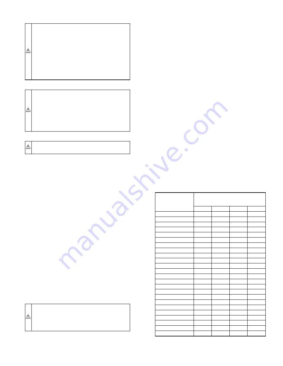
CAUTION:
To prevent compressor damage or personal
injury, observe the following:
• Do not overcharge system with refrigerant.
• Do not operate unit in a vacuum or at negative pressure.
• Do not disable low-pressure switch.
In scroll compressor applications:
• Dome temperatures may be hot.
• In 3-phase application, incorrect phasing will cause
reverse rotation, resulting in elevated noise levels, equal-
ized pressures, and reduced current draw. Correct by
reversing power connection L1 and L2 on contactor.
CAUTION:
To prevent personal injury wear safety
glasses, protective clothing, and gloves when handling
refrigerant and observe the following:
• Back seating service valves are not equipped with
Schrader valves. Fully back seat (counter clockwise)
valve stem before removing gage port cap.
• Front seating service valves are equipped with Schrader
valves.
CAUTION:
Do not vent refrigerant to atmosphere. Re-
cover during system repair or final unit disposal.
1. The outdoor unit is equipped with a crankcase heater which
operates at temperatures less than 75°F. If outdoor tempera-
ture is less than 75°F, energize crankcase heater 24 hr
before starting unit. To energize heater only, set indoor
thermostat to OFF position and close power disconnect to
unit.
2. Fully back seat (open) liquid and vapor tube service valves.
3. Unit is shipped with valve stem(s) front seated and caps
installed. Replace stem caps after system is opened to
refrigerant flow (back seated). Replace caps finger tight and
tighten additional 1/12 turn (20 ft-lb torque) with wrench.
4. Close electrical disconnects to energize system.
5. Set room thermostat at desired temperature. Be sure set
point is below indoor ambient and is set low enough to
energize desired speed.
NOTE:
Bryant electronic thermostats are equipped with a 15-
minute staging timer. This timer prevents the 2-speed system from
operating at high speed until unit has been operating in low speed
for 15 minutes unless there is at least a 5°F difference between
room temperature and thermostat set point. To force high speed
(after a minimum of 2 minutes in low speed), adjust the set point
at least 5° below room ambient.
6. Set room thermostat to COOL and fan control to AUTO or
ON as desired. Wait for appropriate time delay(s) and
2-minute minimum low-speed run time. Operate unit for 15
minutes. Check refrigerant charge.
XI.
CHECK CHARGE
WARNING:
Service valve gage ports are not equipped
with Schrader valves. To prevent personal injury, make
sure gage manifold is connected to the valve gage ports
before moving valves off fully back seated position. Wear
safety glasses and gloves when handling refrigerant.
A.
Unit Charge
Factory charge is shown on unit rating plate.
NOTE:
When 2-speed unit is operating at low speed, system
vapor (suction) pressure will be higher than a standard single-
speed system or high-speed operation. This normal operation is
due to the reduced capacity operating with typically larger indoor
and outdoor coils.
Adjust charge by following procedure shown on charging tables
located on unit.
NOTE:
If superheat or subcooling charging conditions are not
favorable, charge must be weighed in accordance with unit rating
plate
±
0.6 oz/ft of 3/8-in. liquid line above or below 15 ft
respectively.
EXAMPLE:
25 ft - 15 ft = 10 ft X 0.6 oz/ft = 6 oz of additional charge
B.
Cooling Only Procedure
1. Operate unit a minimum of 10 minutes before checking
charge.
2. Measure liquid service valve pressure by attaching an
accurate gage to service port.
3. Measure liquid line temperature by attaching an accurate
thermistor type or electronic thermometer to liquid line near
outdoor coil.
4. Refer to unit rating plate for required subcooling tempera-
ture.
5. Refer to Table 6. Find the point where required subcooling
temperature intersects measured liquid service valve pres-
sure.
6. To obtain required subcooling temperature at a specific
liquid line pressure, add refrigerant if liquid line tempera-
ture is higher than indicated or reclaim refrigerant if
temperature is lower. Allow a tolerance of
±
3°F.
TABLE 6—REQUIRED LIQUID-LINE TEMPERATURE (°F)
LIQUID
PRESSURE AT
SERVICE VALVE
(PSIG)
REQUIRED SUBCOOLING
TEMPERATURE
(°F)
5
10
15
20
134
71
66
61
56
141
74
69
64
59
148
77
72
67
62
156
80
75
70
65
163
83
78
73
68
171
86
81
76
71
179
89
84
79
74
187
92
87
82
77
196
95
90
85
80
205
98
93
88
83
214
101
96
91
86
223
104
99
94
89
233
107
102
97
92
243
110
105
100
95
253
113
108
103
98
264
116
111
106
101
274
119
114
109
104
285
122
117
112
107
297
125
120
115
110
309
128
123
118
113
321
131
126
121
116
331
134
129
124
119
346
137
132
127
122
359
140
135
130
125
—13—


