


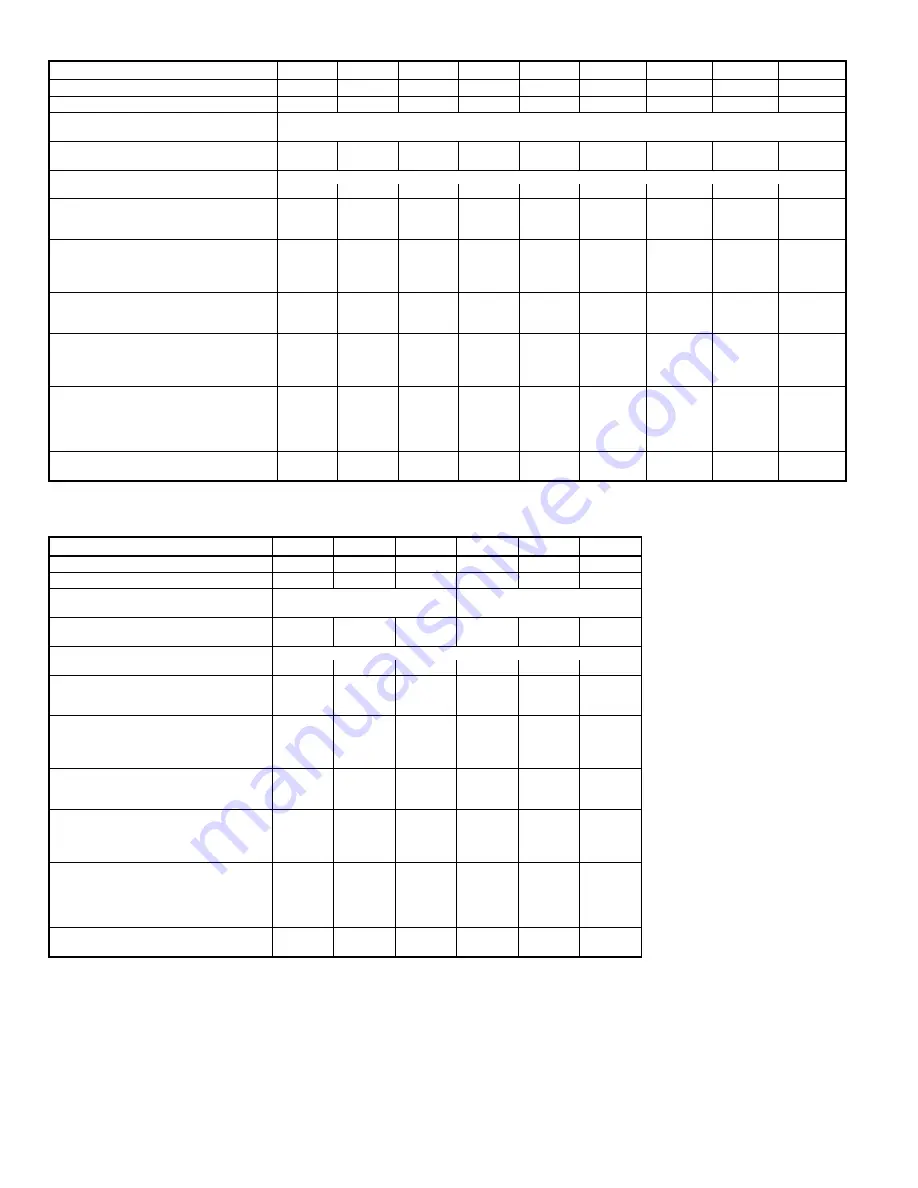
Table 1 — Physical Data — Unit 582A
UNIT SIZE 582A
018040
024040
024060
030040
030060
036060
036090
042060
042090
NOMINAL CAPACITY (ton)
1
1
⁄
2
2
2
2
1
⁄
2
2
1
⁄
2
3
3
3
1
⁄
2
3
1
⁄
2
OPERATING WEIGHT (lb)
249
280
280
280
280
314
314
355
355
COMPRESSORS
Reciprocating
Quantity
1
REFRIGERANT (R-22)
Quantity (lbs)
2.6
3.5
3.5
3.65
3.65
3.75
3.75
5.7
5.7
REFRIGERANT METERING DEVICE
Acutrol™ Device
Orifice ID (in.)
.034
.034
.034
.034
.034
.032
.032
.034
.034
CONDENSER COIL
Rows...Fins/in.
1...17
1...17
1...17
1...17
1...17
1...17
1...17
1...17
1...17
Face Area (sq ft)
6.1
9.1
9.1
9.1
9.1
9.1
9.1
9.1
9.1
CONDENSER FAN
Nominal Cfm
2000
2400
2400
2400
2400
3000
3000
3000
3000
Diameter (in.)
22
22
22
22
22
22
22
22
22
Motor Hp (Rpm)
1
⁄
8
(825)
1
⁄
8
(825)
1
⁄
8
(825)
1
⁄
8
(825)
1
⁄
8
(825)
1
⁄
4
(1100)
1
⁄
4
(1100)
1
⁄
4
(1100)
1
⁄
4
(1100)
EVAPORATOR COIL
Rows...Fins/in.
2...15
2...15
2...15
2...15
2...15
3...15
3...15
4...15
4...15
Face Area (sq ft)
3.1
3.1
3.1
3.1
3.1
3.1
3.1
3.1
3.1
EVAPORATOR BLOWER
Nominal Airflow (Cfm)
600
800
800
1000
1000
1200
1200
1400
1400
Size (in.)
10 x 10
10 x 10
10 x 10
10 x 10
10 x 10
11 x 10
11 x 10
11 x 10
11 x 10
Motor (Hp)
1
⁄
4
1
⁄
4
1
⁄
4
1
⁄
4
1
⁄
4
1
⁄
2
1
⁄
2
3
⁄
4
3
⁄
4
FURNACE SECTION*
Burner Orifice No. (Qty...Drill Size)
Natural Gas
2...45
2...45
2...38
2...45
2...38
2...38
3...38
2...38
3...38
Burner Orifice No. (Qty...Drill Size)
Propane Gas
2...50
2...50
2...46
2...50
2...46
2...46
3...46
2...46
3...46
RETURN-AIR FILTERS (in.)†
Throwaway
20 x 20
20 x 20
20 x 20
20 x 20
20 x 20
20 x 24
20 x 24
20 x 24
20 x 24
UNIT SIZE 582A
048090
048115
048130
060090
060115
060130
NOMINAL CAPACITY (ton)
4
4
4
5
5
5
OPERATING WEIGHT (lb)
415
415
415
450
450
450
COMPRESSORS
Scroll
Reciprocating
Quantity
1
1
REFRIGERANT (R-22)
Quantity (lbs)
6.0
6.0
6.0
8.0
8.0
8.0
REFRIGERANT METERING DEVICE
Acutrol Device
Orifice ID (in.)
.032
.032
.032
.030
.030
.030
CONDENSER COIL
Rows...Fins/in.
1...17
1...17
1...17
2...17
2...17
2...17
Face Area (sq ft)
12.3
12.3
12.3
12.3
12.3
12.3
CONDENSER FAN
Nominal Cfm
3600
3600
3600
3600
3600
3600
Diameter (in.)
22
22
22
22
22
22
Motor Hp (Rpm)
1
⁄
4
(1100)
1
⁄
4
(1100)
1
⁄
4
(1100)
1
⁄
4
(1100)
1
⁄
4
(1100)
1
⁄
4
(1100)
EVAPORATOR COIL
Rows Fins...in.
3...15
3...15
3...15
4...15
4...15
4...15
Face Area (sq ft)
4.7
4.7
4.7
4.7
4.7
4.7
EVAPORATOR BLOWER
Nominal Airflow (Cfm)
1600
1600
1600
2000
2000
2000
Size (in.)
11 x 10
11 x 10
11 x 10
11 x 10
11 x 10
11 x10
Motor (hp)
3
⁄
4
3
⁄
4
3
⁄
4
1.0
1.0
1.0
FURNACE SECTION*
Burner Orifice No. (Qty...Drill Size)
Natural Gas
3...38
3...33
3...31
3...38
3...33
3...31
Burner Orifice No. (Qty...Drill Size)
Propane Gas
3...46
3...42
3...41
3...46
3...42
3...41
RETURN-AIR FILTERS (in.)†
Throwaway
24 x 30
24 x 30
24 x 30
24 x 30
24 x 30
24 X 30
*Based on altitude of 0 to 2000 feet.
†Required filter sizes shown are based on the larger of the ARI (Air Conditioning
and Refrigeration Institute) rated cooling airflow or the heating airflow velocity of
300 ft/min for throwaway type or 450 ft/min for high-capacity type. Air filter pressure
drop for non-standard filters must not exceed 0.08 in. wg.
—8—
Summary of Contents for 582A Series
Page 26: ...Fig 29 Cooling Charging Chart 583A048 Units Fig 30 Cooling Charging Chart 583A060 Units 26 ...
Page 36: ......
Page 37: ......
Page 39: ......


