background image

SERVICE

CAUTION:

When servicing unit, shut off all electri-

cal power to unit to avoid shock hazard or injury from
rotating parts.

I. CLEANING

Inspect unit interior at the beginning of each cooling season
and as operating conditions require.

A. Outdoor Coil

Inspect coil monthly. Clean outdoor coil annually and as re-
quired by location or outdoor-air conditions.

Clean coil as follows:

1. Turn off unit power.

2. Remove and save top panel screws on outdoor unit.

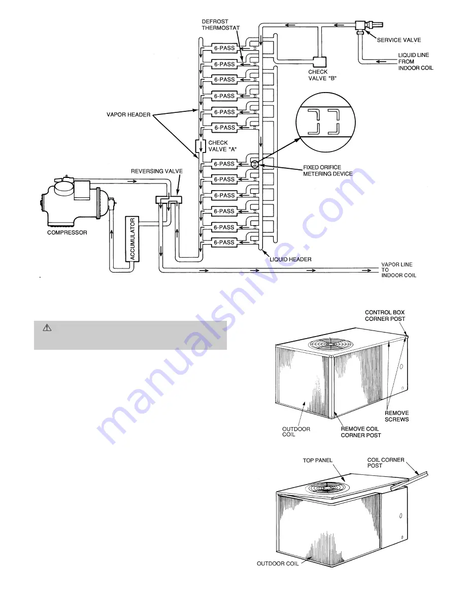
3. Remove outdoor coil corner post. See Fig. 14. To hold

top panel open, place coil corner post between top panel
and side panel. See Fig. 15.

4. Remove bracket holding coil sections together at return

end of outdoor coil. Carefully separate the outer coil sec-
tion 3 to 4 in. from the inner coil section. See Fig. 16.

5. Use a water hose or other suitable equipment to flush

down between the 2 coil sections to remove dirt and de-
bris. Clean the outer surfaces with a stiff brush in the
normal manner.

6. Reposition the outer coil section and secure the sections

together. Remove the coil corner post from between the
top panel and side panel. Install the coil corner post and
replace all screws removed in Step 2.

Fig. 13 — Heating Mode Operation

Fig. 14 — Cleaning Outdoor Coil

Fig. 15 — Propping Up Top Panel

—11—

Summary of Contents for 575A

Page 1: ...al installation requirements WARNING Before installing or servicing system al ways turn off main power to system There may be more than one disconnect switch Electrical shock can cause personal injury INSTALLATION The 575A090 unit uses a semi hermetic compressor See Table 1 for physical data The 575A090 outdoor unit is approved for use only with the 524A H090 indoor unit Use only approved indoor u...

Page 2: ...arance is optional c Overhead 60 in 1524 mm to assure proper outdoor fan operation d Between units control box side 42 in 1067 mm per National Electrical Code NEC e Between unit and ungrounded surfaces control box side 36 in 914 mm per NEC f Between unit and block or concrete walls and other grounded surfaces control box side 42 in 1067 mm per NEC 5 With the exception of the clearance for the outd...

Page 3: ...red if top crating is left on unit All panels must be in place when rigging See Fig 3 As further protection for coil faces plywood sheets may be placed against sides of unit behind cables Run cables to a central suspension point so that angle from the horizontal plane is not less than 45 degrees Raise and set unit down carefully If it is necessary to roll unit into position mount unit on rails usi...

Page 4: ...ed NOTE Unit is shipped with R 22 holding charge System pres sure must be relieved before removing caps Recover refrig erant prior to brazing Pass nitrogen or other inert gas through piping while braz ing to prevent formation of copper oxide C Liquid Line Solenoid Valve A field supplied liquid line solenoid valve LLSV is recom mended when piping system length exceeds 75 feet The LLSV must be of th...

Page 5: ...n are general points of connection guides only and are not intended for or to include all details for a spe cific installation 4 Liquid line solenoid valve solenoid drop control is recom mended to prevent refrigerant migration to the compressor A bi flow type solenoid valve is required 5 Filter drier must be of the biflow type suitable for heat pump duty 6 Internal factory supplied TXV and bypass ...

Page 6: ... for field wire connections Use factory supplied splices or UL approved copper aluminum connector When installing units provide a disconnect per NEC All field wiring must comply with NEC and local requirements Install field wiring as follows 1 Install conduit through side panel openings 2 Install power lines to connections as shown in Fig 8 Wrap connections with electrical tape Voltage to compress...

Page 7: ...balance 100 457 1 53 This amount of phase imbalance is satisfactory as it is below the maximum allowable 2 IMPORTANT If the supply voltage phase imbalance is more than 2 contact your local electric utility company immediately Table 5 Accessory Electric Heater Data UNIT 524A H NOMINAL kW V PH HZ HEATER PART NO HEATER AMPS MCA MOCP 090 5 240 3 60 CAELHEAT001A00 12 0 25 6 30 480 3 60 CAELHEAT002A00 6...

Page 8: ...operate for at least 24 hours be fore start up 6 Note that compressor oil level is visible in the sight glass 7 Check for leaks in refrigerant system by using soap bubbles and or electronic leak detector 8 Check voltage imbalance as shown in Table 4 Note 2 9 Check that both outdoor and indoor units are properly mounted in accordance with installation instructions and applicable codes II EVACUATE A...

Page 9: ...lows through from the liquid header side outlets into the transfer header where it flows upward 4 Refrigerant leaves the transfer header through side con nections in 4 locations and enters the middle coil cir cuits 4 coil circuits above check valve A 5 Refrigerant leaves the 4 middle coil circuits and enters the top portion of vapor header The refrigerant moves up to the top 2 remaining coil circu...

Page 10: ... Observe that compressor outdoor fan indoor fan motor and electric heaters if equipped start Observe that heating cycle shuts down when control set ting is satisfied 4 When using an automatic changeover room thermostat place both SYSTEM and FAN switches in AUTO posi tions Observe that unit operates in Cooling mode when temperature control is set to call for cooling below room temperature and unit ...

Page 11: ... place coil corner post between top panel and side panel See Fig 15 4 Remove bracket holding coil sections together at return end of outdoor coil Carefully separate the outer coil sec tion 3 to 4 in from the inner coil section See Fig 16 5 Use a water hose or other suitable equipment to flush down between the 2 coil sections to remove dirt and de bris Clean the outer surfaces with a stiff brush in...

Page 12: ... unit 2 Remove refrigerant from system using refrigerant re moval methods described in Refrigerant Service Tech niques manual 3 Disconnect compressor wiring at compressor terminal box Disconnect high pressure switch 4 Remove bolts from discharge service valve and suction flange CAUTION Excessive movement of copper lines at compressor may cause higher levels of vibration when unit is restored to se...

Page 13: ...TROUBLESHOOTING CHART HEATING CYCLE LEGEND N C Normally Closed 13 ...

Page 14: ...TROUBLESHOOTING CHART COOLING CYCLE LEGEND TXV Thermostatic Expansion Valve Copyright 1995 Carrier Corporation CATALOG NO BDP 3357 502 ...

Page 15: ...N ARE PROPER AIR FILTERS IN PLACE Y N HAVE FAN AND MOTOR PULLEYS BEEN CHECKED FOR PROPER ALIGNMENT Y N DO THE FAN BELTS HAVE PROPER TENSION Y N HAS CORRECT FAN ROTATION BEEN CONFIRMED Y N PIPING IS LIQUID LINE SOLENOID VALVE LOCATED AT THE OUTDOOR UNIT AS RECOMMENDED Y N HAVE LEAK CHECKS BEEN MADE AT COMPRESSOR OUTDOOR COIL INDOOR COIL TXV Thermostatic Expansion Valve SOLENOID VALVES FILTER DRIER ...

Page 16: ...ESSURE SUCTION PRESSURE SUCTION LINE TEMP DISCHARGE PRESSURE DISCHARGE LINE TEMP ENTERING OUTDOOR AIR TEMP LEAVING OUTDOOR AIR TEMP INDOOR ENTERING AIR DB dry bulb TEMP INDOOR ENTERING AIR WB wet bulb TEMP INDOOR LEAVING AIR DB TEMP INDOOR LEAVING AIR WB TEMP COMPRESSOR AMPS L1 L2 L3 NOTES CUT ALONG DOTTED LINE Copyright 1995 Carrier Corporation CATALOG NO BDP 3357 502 CL 2 ...

Reviews: