Bryant 569C Installation, Start-Up And Service Instructions Manual Download Page 8

Table 4 — Electrical Data

UNIT

NOMINAL VOLTAGE

(V-Ph-Hz)

VOLTAGE RANGE

COMPRESSOR

OFM

POWER SUPPLY

Min

Max

RLA

LRA

FLA

MCA

MOCP

569C072

208/230-3-60

187

254

21.8

142

1.9

25.6

35

460-3-60

414

508

9.6

72

1.0

12.9

15

575-3-60

518

632

7.6

58

1.9

11.4

15

220-3-50

198

242

19.0

142

1.0

25.6

35

400-3-50

360

440

9.5

72

1.0

12.9

15

569C090

208/230-3-60

187

254

28.8

195

3.8

39.8

45

460-3-60

414

508

14.7

95

1.9

20.3

20

575-3-60

518

632

10.8

80

1.9

15.4

15

220-3-50

198

242

28.8

195

1.5

37.5

45

400-3-50

360

440

14.7

90

1.5

19.9

20

569C120

208/230-3-60

187

254

37.8

239

3.1

46.2

60

460-3-60

414

508

17.2

125

1.4

22.7

30

575-3-60

518

632

12.3

80

1.4

19.3

25

220-3-50

198

242

37.8

239

1.4

46.2

60

400-3-50

360

440

17.2

114

1.4

22.7

30

576B090

208/230-3-60

187

254

31.5

160

3.1

42.5

50

380-3-60

342

418

19.0

75

2.2

26.0

35

460-3-60

414

508

15.7

80

1.4

21.0

25

575-3-60

518

632

12.6

64

1.4

17.2

20

220-3-50

198

253

31.5

160

1.4

42.5

50

400-3-50

342

460

15.7

80

1.4

21.0

25

576B102

208/230-3-60

187

254

39.7

198

3.1

52.7

70

380-3-60

342

418

24.0

93

2.2

32.2

40

460-3-60

414

508

19.9

99

1.4

26.3

35

575-3-60

518

632

15.9

79

1.4

21.3

25

220-3-50

198

253

39.7

198

1.4

52.7

70

400-3-50

342

460

19.9

99

1.4

26.3

35

576B120

208/230-3-60

187

254

39.7

198

3.1

52.7

70

380-3-60

342

418

24.0

93

2.2

32.2

40

460-3-60

414

508

19.9

99

1.4

26.3

35

575-3-60

518

632

15.9

79

1.4

21.3

25

220-3-50

198

253

39.7

198

1.4

52.7

70

400-3-50

342

460

19.9

99

1.4

26.3

35

LEGEND

CSA

— Canadian Standards Association

FLA

— Full Load Amps

HACR — Heating, Air Conditioning and Refrigeration
LRA

— Locked Rotor Amps

MCA

— Minimum Circuit Amps

MOCP — Maximum Overcurrent Protection
NEC

— National Electrical Code (U.S.A. Standard)

OFM

— Outdoor (Condenser) Fan Motor

RLA

— Rated Load Amps

UL

— Underwriters’ Laboratories

NOTES:
1. In compliance with NEC requirements for multimotor and combina-

tion load equipment (refer to NEC Articles 430 and 440), the over-
current protective device for the unit shall be fuse or HACR breaker.

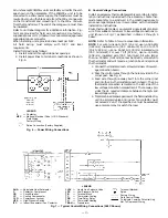
2. Unbalanced 3-Phase Supply Voltage

Never operate a motor where a phase imbalance in supply voltage is
greater than 2%.

Use the following formula to determine the percent

voltage imbalance.

max voltage deviation from average voltage

= 100 x

average voltage

Example: Supply voltage is 460-3-60.

AB = 452 v
BC = 464 v
AC = 455 v

452 + 464 + 455

Average Voltage =

3

1371

=

3

= 457

(AB) 457 - 452 = 5 v
(BC) 464 - 457 = 7 v
(AC) 457 - 455 = 2 v
Maximum deviation is 7 v.
Determine percent voltage imbalance

7

% Voltage Imbalance = 100 x

457

= 1.53%

This amount of phase imbalance is satisfactory as it is below the maxi-
mum allowable 2%.
IMPORTANT: If the supply voltage phase imbalance is more than 2%,
contact your local electric utility company immediately.

3. The 575-v units are CSA only.
4. The 380-v units are

not

UL or CSA listed.

—8—

Summary of Contents for 569C

Page 1: ...otential for per sonal injury Understand the signal words DANGER WARNING and CAUTION These words are used with the safety alert sym bol Danger identifies the most serious hazards which will result in severe personal injury or death Warning indicates a condition that could result in personal injury Caution is used to identify unsafe practices which would result in minor personal injury or product a...

Page 2: ...ides of unit behind cables Run cables to a central suspension point so that angle from the horizontal is not less than 45 degrees Raise and set unit down carefully If it is necessary to roll unit into position mount unit on lon gitudinal rails using a minimum of 3 rollers Apply force to rails not unit If unit is to be skidded into position place it on a large pad and drag it by the pad Do not appl...

Page 3: ... Drive Quantity Rpm 1 850 1 1100 Diameter in 26 26 Motor Hp NEMA 1 3 3 4 Nominal Airflow cfm 3800 6500 7000 6500 6500 6500 CONDENSER COIL Enhanced Copper Tubes Aluminum Lanced Fins Face Area sq ft 12 24 15 75 20 5 18 0 18 0 18 0 Storage Capacity lb 11 26 14 88 18 87 16 56 16 56 16 56 CONNECTIONS sweat Suction in 11 8 11 8 11 8 11 8 11 8 11 8 Liquid in 1 2 1 2 5 8 1 2 5 8 5 8 CONTROLS Pressurestat ...

Page 4: ... 660 660 Motor Hp NEMA 1 3 3 4 Nominal Airflow L s 1800 3050 3300 3050 3050 3050 CONDENSER COIL Enhanced Copper Tubes Aluminum Lanced Fins Face Area sq m 1 14 1 46 1 90 1 67 1 67 1 67 Storage Capacity kg 5 1 6 75 8 6 7 5 7 5 7 5 CONNECTIONS sweat Suction in 11 8 11 8 11 8 11 8 11 8 11 8 Liquid in 1 2 1 2 5 8 1 2 5 8 5 8 CONTROLS Pressurestat Settings kPa High Cutout 2937 6 48 Cut in 2206 6 138 Low...

Page 5: ...r The left or rear side getting the greater clearance is optional b Overhead 60 in 1524 to assure proper condenser fan operation c Between units control box side 42 in 1067 per NEC National Electrical Code U S A Standard d Between unit and ungrounded surfaces con trol box side 36 in 914 per NEC e Between unit and block or concrete walls and other grounded surfaces control box side 42 in 1067 per N...

Page 6: ... 3 7 48 3 2 1 576B090 60 18 3 7 48 3 2 1 576B102 65 19 8 7 48 3 2 1 576B120 65 19 8 7 48 3 2 1 NOTE Values shown are for units operating at 45 F 7 2 C saturated suction and 95 F 35 C entering air V ELECTRICAL CONNECTIONS WARNING The unit cabinet must have an uninter rupted unbroken electrical ground to minimize the pos sibility of personal injury if an electrical fault should occur This ground may...

Page 7: ...minimum For 50 to 75 ft 15 2 to 22 9 m use no 16 AWG 1 30 mm insulated wire 35 C minimum For over 75 ft 22 9 m use no 14 AWG 2 08 mm insulated wire 35 C minimum All wire larger than no 18 AWG 0 82 mm cannot be directly connected to the thermostat and will require a junction box and splice at the thermostat 1 Connect thermostat wires to screw terminals of low volt age connection board 2 Pass the co...

Page 8: ...0 93 2 2 32 2 40 460 3 60 414 508 19 9 99 1 4 26 3 35 575 3 60 518 632 15 9 79 1 4 21 3 25 220 3 50 198 253 39 7 198 1 4 52 7 70 400 3 50 342 460 19 9 99 1 4 26 3 35 LEGEND CSA Canadian Standards Association FLA Full Load Amps HACR Heating Air Conditioning and Refrigeration LRA Locked Rotor Amps MCA Minimum Circuit Amps MOCP Maximum Overcurrent Protection NEC National Electrical Code U S A Standar...

Page 9: ...ything inside terminal box 5 Never attempt to repair soldered connection while refrigerant system is under pressure 6 Do not use torch to remove any component Sys tem contains oil and refrigerant under pressure To remove a component wear protective goggles and proceed as follows a Shut off electrical power to unit b Recover refrigerant Relieve all pressure from system c Cut component connecting tu...

Page 10: ...4v indoor evaporator fan contactor to function A field supplied and installed liquid line valve connected between Terminals G and C will also open allowing the system to function in cooling As cooling demand is satisfied the ther mostat contacts break deenergizing the contactor causing the system to shut off The liquid line solenoid LLS valve closes minimizing the potential for refrigerant migrati...

Page 11: ...is Clean the outer surfaces with a stiff brush in the normal manner 6 Reposition the outer coil section attach the bracket re moved in Step 4 and remove the coil corner post from between the top panel and side panel Secure the sec tions together Install the coil corner post and replace all screws removed in Step 2 II LUBRICATION A Compressors Each compressor is charged with the correct amount of o...

Page 12: ...en compressor is not operating Close both compressor service valves if applicable when crank case heater is deenergized for more than 6 hours VII REFRIGERANT CHARGE Unit panels must be in place when unit is operating during charging procedure Unit is shipped with a holding charge only Weigh in 7 lbs 3 kg of R 22 to start unit Refer to GTAC II Module 5 Charging Recovery Recycling and Reclamation fo...

Page 13: ...Fig 14 Cooling Charging Chart 569C072 Fig 15 Cooling Charging Chart 569C090 120 and 576B090 102 120 13 ...

Page 14: ...shaft Tighten fan hub screws Motor not running Check power and capacitor 1 3 and 3 4 hp motor Motor bearings seized Replace motor Motor overload open Check overload rating Check for fan blade obstruction Motor burned out windings open Replace motor Compressor cycles on low pressure switch Evaporator fan running Filter drier plugged Replace filter drier Expansion valve power head defective Replace ...

Page 15: ...itch LPS Low Pressure Switch NEC National Electrical Code OFC Outdoor Condenser Fan Contactor OFM Outdoor Condenser Fan Motor OL Overload Relay QT Quadruple Terminal TB Terminal Block TDR Time Delay Relay TRAN Transformer Terminal Marked Terminal Unmarked Terminal Block Factory Wiring Field Power Wiring Fig 16 Typical 569C Wiring Schematic and Component Arrangement Fig 17 Typical 576B Wiring Schem...

Page 16: ......

Page 17: ......

Page 18: ...Copyright 1999 Bryant Heating Cooling Systems CATALOG NO 5356 902 ...

Page 19: ...N ARE PROPER AIR FILTERS IN PLACE Y N HAVE FAN AND MOTOR PULLEYS BEEN CHECKED FOR PROPER ALIGNMENT Y N DO THE FAN BELTS HAVE PROPER TENSION Y N HAS CORRECT FAN ROTATION BEEN CONFIRMED Y N PIPING IS LIQUID LINE SOLENOID VALVE LOCATED AT THE EVAPORATOR COIL AS REQUIRED Y N HAVE LEAK CHECKS BEEN MADE AT COMPRESSOR CONDENSER EVAPORATOR TXVs Thermostatic Expansion Valves SOLENOID VALVES FILTER DRIERS A...

Page 20: ...URE SUCTION LINE TEMP DISCHARGE PRESSURE DISCHARGE LINE TEMP ENTERING CONDENSER AIR TEMP LEAVING CONDENSER AIR TEMP EVAP ENTERING AIR DB dry bulb TEMP EVAP ENTERING AIR WB wet bulb TEMP EVAP LEAVING AIR DB TEMP EVAP LEAVING AIR WB TEMP COMPRESSOR AMPS L1 L2 L3 HAS REFRIGERANT CHARGE BEEN ADJUSTED PER UNIT CHARGING CHART NOTES Copyright 1999 Bryant Heating Cooling Systems CATALOG NO 5356 902 CL 2 ...

Reviews: