


Table 1A — Specifications (English)
UNIT
569C072
569C090
569C120
576B090
576B102
576B120
NOMINAL CAPACITY (Tons)
6
7
1
⁄
2
10
7
1
⁄
2
8
1
⁄
2
10
OPERATING WEIGHT (lb)
Aluminum Coils (Standard)
340
370
395
510
564
564
Copper Coils (Optional)
386
438
472
578
632
632
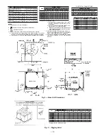
RIGGING WEIGHT (lb)
Aluminum Coils (Standard)
390
420
445
560
614
614
Copper Coils (Optional)
436
488
522
628
682
682
REFRIGERANT*
R-22
COMPRESSOR
Bristol, Reciprocating
Copeland, Scroll
Copeland, Scroll
Reciprocating, Semi-Hermetic
Quantity...Type
1...H26A72Q
1...ZR94KC
1...ZR125KC
1...06DA818
1...06DA824
1...06DH824
(See Note)
Quantity Cylinders
2
—
—
4
6
Speed (Rpm)
3500
3500
3500
1750
1750
Oil Charge (oz) (ea)
65
85
110
88
128
CONDENSER FAN
Propeller; Direct Drive
Quantity...Rpm
1...850
1...1100
Diameter (in.)
26
26
Motor Hp (NEMA)
1
⁄
3
3
⁄
4
Nominal Airflow (cfm)
3800
6500
7000
6500
6500
6500
CONDENSER COIL
Enhanced Copper Tubes, Aluminum Lanced Fins
Face Area (sq ft)
12.24
15.75
20.5
18.0
18.0
18.0
Storage Capacity (lb)†
11.26
14.88
18.87
16.56
16.56
16.56
CONNECTIONS (sweat)
Suction (in.)
1
1
⁄
8
1
1
⁄
8
1
1
⁄
8
1
1
⁄
8
1
1
⁄
8
1
1
⁄
8
Liquid (in.)
1
⁄
2
1
⁄
2
5
⁄
8
1
⁄
2
5
⁄
8
5
⁄
8
CONTROLS
Pressurestat Settings (psig)
High Cutout
426
6
7
Cut-in
320
6
20
Low Cutout
7
6
3
Cut-in
22
6
5
LEGEND
NEMA — National Electrical Manufacturing Association
*Unit is factory supplied with holding charge only.
†Storage capacity of condenser coil with coil 80% full of liquid R-22 at
124 F.
NOTE: Unit 576B120 has one step of unloading. Full load is 100% ca-
pacity, and one step of unloading is 67% capacity. Unit 576B120 has
the following unloader settings: load is 70
6
1 psig and unload is
60
6
2 psig.
—3—
Summary of Contents for 569C
Page 16: ......
Page 17: ......
Page 18: ...Copyright 1999 Bryant Heating Cooling Systems CATALOG NO 5356 902 ...


