Bryant 311AAV Series 100 Installation, Start-Up, Operating And Service And Maintenance Instructions Download Page 6

Step 2—General Installation

US: Current edition of the NFGC and the NFPA 90B. For
copies, contact the National Fire Protection Association Inc.,
Batterymarch Park, Quincy, MA 02269; (www.NFPA.org) or
for only the NFGC, contact the American Gas Association, 400
N. Capitol Street, N.W., Washington, DC 20001
(www.AGA.org).

CANADA: NSCNGPIC. For a copy, contact Standard Sales,
CSA International, 178 Rexdale Boulevard, Etobicoke (Tor-
onto), Ontario, M9W 1R3 Canada

Step 3—Combustion and Ventilation Air

US: Section 8.3 of the NFGC, Air for Combustion and
Ventilation

CANADA: Part 7 of NSCNGPIC, Venting Systems and Air
Supply for Appliances

Step 4—Duct Systems

US and CANADA: Air Conditioning Contractors Association
(ACCA) Manual D, Sheet Metal and Air Conditioning Con-
tractors National Association (SMACNA), or American Soci-
ety of Heating, Refrigeration, and Air Conditioning Engineers
(ASHRAE) 2001 Fundamentals Handbook Chapter 34 or 2000
HVAC Systems and Equipment Handbook Chapters 9 and 16.

Step 5—Acoustical Lining and Fibrous Glass Duct

US and CANADA: current edition of SMACNA and NFPA
90B as tested by UL Standard 181 for Class I Rigid Air Ducts

Step 6—Gas Piping and Gas Pipe Pressure Testing

US: NFGC; chapters 5, 6, 7, and 12 and National Plumbing
Codes

CANADA: NSCNGPIC Parts 3, 4, and 5, and Appendices A,
B, E, and H.

Step 7—Electrical Connections

US: National Electrical Code (NEC) ANSI/NFPA 70–2002

CANADA: Canadian Electrical Code CSA C22.1

Step 8—Venting

US: NFGC; chapters 10 and 13

CANADA: NSCNGPIC Part 7 and Appendix C

ELECTROSTATIC DISCHARGE (ESD) PRECAUTIONS

PROCEDURE

FURNACE RELIABILITY HAZARD
Improper installation or service of furnace may cause prema-
ture furnace component failure.
Electrostatic discharge can affect electronic components.
Follow the Electrostatic Discharge Precautions Procedure
listed below during furnace installation and servicing to
protect the furnace electronic control. Precautions will pre-
vent electrostatic discharges from personnel and hand tools
which are held during the procedure. These precautions will
help to avoid exposing the control to electrostatic discharge
by putting the furnace, the control, and the person at the same
electrostatic potential.

1. Disconnect all power to the furnace. Multiple disconnects may

be required. DO NOT TOUCH THE CONTROL OR ANY
WIRE CONNECTED TO THE CONTROL PRIOR TO DIS-
CHARGING YOUR BODY’S ELECTROSTATIC CHARGE
TO GROUND.

2. Firmly touch the clean, unpainted, metal surface of the furnace

chassis which is close to the control. Tools held in a person’s
hand during grounding will be satisfactorily discharged.

3. After touching the chassis, you may proceed to service the

control or connecting wires as long as you do nothing to
recharge your body with static electricity (for example; DO
NOT move or shuffle your feet, do not touch ungrounded
objects, etc.).

4. If you touch ungrounded objects (and recharge your body with

static electricity), firmly touch a clean, unpainted metal
surface of the furnace again before touching control or wires.

5. Use this procedure for installed and uninstalled (ungrounded)

furnaces.

6. Before removing a new control from its container, discharge

your body’s electrostatic charge to ground to protect the
control from damage. If the control is to be installed in a
furnace, follow items 1 through 4 before bringing the control
or yourself in contact with the furnace. Put all used and new
controls into containers before touching ungrounded objects.

7. An ESD service kit (available from commercial sources) may

also be used to prevent ESD damage.

LOCATION

GENERAL

This multipoise furnace is shipped in packaged configuration.
Some assembly and modifications are required when used in any
of the four applications shown in Fig. 4.

This furnace must:

be installed so the electrical components are protected from
water.

not be installed directly on any combustible material other than
wood flooring (refer to SAFETY CONSIDERATIONS).

be located as close to the chimney or vent and attached to an air
distribution system. Refer to Air Ducts section.

be provided ample space for servicing and cleaning. Always
comply with minimum fire protection clearances shown on the
furnace clearance to combustible label.

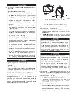
Fig. 3—Return Air Temperature

A02055

60

5

Summary of Contents for 311AAV Series 100

Page 1: ...ing in sensitive applications The 311AAV JAV furnace is approved for use with natural or propane gas and the 311JAV is also approved for use in Low NOx Air Quality Management Districts STANDARD FEATUR...

Page 2: ...Installation 10 Bottom Return Air Inlet 11 Horizontal Installation 12 Suspended Unit Support 12 Platform Unit Support 12 Roll Out Protection 12 Bottom Return Air Inlet 13 Side Return Air Inlet 13 Fil...

Page 3: ...ervice calls This is the safety alert symbol When you see this symbol on the furnace and in instructions or manuals be alert to the potential for personal injury Understand the signal words DANGER WAR...

Page 4: ...gn certified A Category I fan assisted furnace is an appliance equipped with an integral mechanical means to either draw or force products of combustion through the combustion chamber and or heat exch...

Page 5: ...ommun d autres appareils gaz MINIMUM INCHES CLEARANCE TO COMBUSTIBLE CONSTRUCTION Installation on non combusibible floors only For Installation on combustible flooring only when installed on special...

Page 6: ...recautions will help to avoid exposing the control to electrostatic discharge by putting the furnace the control and the person at the same electrostatic potential 1 Disconnect all power to the furnac...

Page 7: ...lvents such as perchloroethylene Printing inks paint removers varnishes etc Hydrochloric acid Cements and glues Antistatic fabric softeners for clothes dryers Masonry acid washing materials All fuel b...

Page 8: ...must be installed parallel with or on the downstream side of the unit to avoid condensation in the heat exchangers When installed parallel with the furnace dampers or other flow control must prevent...

Page 9: ...nace combustion air supply must be provided in accordance with this instruction manual The Standard Method 1 The space has no less volume than 50 cubic feet per 1 000 Btuh of the maximum input ratings...

Page 10: ...hin 12 300 mm of the floor The minimum dimension of air openings shall be at least 3 in 80 mm See Fig 8 c Combining space on different floor levels The volumes of spaces on different floor levels shal...

Page 11: ...m closure panel perform the following 1 Tilt or raise furnace and remove 2 screws holding bottom filler panel See Fig 9 2 Rotate bottom filler panel downward to release holding tabs 3 Remove bottom cl...

Page 12: ...lled in bottom return air opening Remove and discard this panel when bottom return air is used To remove bottom closure panel perform the following 1 Tilt or raise furnace and remove 2 screws holding...

Page 13: ...to joists The sheet metal MUST extend underneath the furnace casing by 1 in with the door removed The bottom closure panel on furnaces of widths 17 1 2 in and larger may be used for flame roll out pr...

Page 14: ...the design external static pressure The furnace airflow rates are provided in Table 5 AIR DELIVERY CFM With Filter When a furnace is installed so that the supply ducts carry air circulated by the furn...

Page 15: ...ply side air duct humidifier or other accesso ries All accessories MUST be connected to duct external to furnace casing Return Air Connections FIRE HAZARD Failure to follow this warning could cause a...

Page 16: ...CREWS IN SIDE AND 2 SCREWS IN BOTTOM Fig 17 Typical Attic Installation A03177 30 IN MIN WORK AREA 6 MIN TYPE B VENT 17 3 4 22 SHEET METAL SEDIMENT TRAP EQUIPMENT MANUAL SHUT OFF GAS VALVE LINE CONTACT...

Page 17: ...880 1715 2130 1995 1805 1645 2025 1895 1730 1565 1920 1785 1630 1480 1790 1675 1535 1390 1660 1565 1420 1280 1530 1420 1275 1145 1350 1260 1135 1005 Both Sides or 1 Side Bottom High Med High Med Low L...

Page 18: ...upstream of gas supply connection to furnace and downstream of manual equipment shutoff valve NOTE The furnace gas control valve inlet pressure tap connec tion is suitable to use as test gauge connect...

Page 19: ...A02075 Fig 18 Upflow Return Air Configurations and Restrictions A02163 Fig 19 Downflow Return Air Configurations and Restrictions A02162 Fig 20 Horizontal Return Air Configurations and Restrictions 18...

Page 20: ...rmitted by local code when installed in accordance with existing electrical codes Refer to the power cord manufacturer s ratings for proper wire gauge Do not use gas piping as an electrical ground FUR...

Page 21: ...Box Do not pinch wires between cover and bracket Electrical Box on Furnace Casing Side See Fig 23 FIRE OR ELECTRICAL SHOCK HAZARD Failure to follow this warning could result in personal injury death o...

Page 22: ...s between cover and bracket 24 V WIRING Make field 24 v connections at the 24 v terminal strip See Fig 23 Connect terminal Y Y2 as shown in Fig 24 for proper cooling operation Use only AWG No 18 color...

Page 23: ...NAL 24 VAC 0 5 AMP MAX TWINNING AND OR COMPONENT TEST TERMINAL BLOWER OFF DELAY Fig 25 Heating and Cooling Application Wiring Diagram with 1 Stage Thermostat A99440 115 V FIELD SUPPLIED DISCONNECT AUX...

Page 24: ...potential for vent gas leakage Category I furnaces operate with a flue loss not less than 17 percent to minimize the potential for condensation in the venting system These furnaces are approved for c...

Page 25: ...ed Air Conditioner A04216 See notes 2 5 8 and 10 on the page following these figures See notes 1 2 4 6 7 9 10 and 12 on the page following these figures A04217 Fig 28 Single Stage Furnace with Single...

Page 26: ...ingle Speed Heat Pump HUMIDFIER 24VAC See notes 1 2 3 4 11 12 and 14 on the page following these figures A04220 Fig 31 Dual Fuel Thermostat with Single Stage Furnace and Two Speed Heat Pump HUMIDFIER...

Page 27: ...default 7 Dip switch No 2 on Thermidistat should be set in ON position for two speed compressor operation 8 Configuration Option No 10 Dual Fuel Selection must be turned ON in all dual fuel applicati...

Page 28: ...ween the chimney and the metal liner APPLIANCE APPLICATION REQUIREMENTS Appliance operation has a significant impact on the performance of the venting system If the appliances are sized installed adju...

Page 29: ...lignment missing sections gaps Debris in cleanout Mortar tile metal vent fuel oil residue Is liner and top seal in good condition Is chimney property lined with clay tile liner Crown condition Missing...

Page 30: ...f flue extension is used fasten the flue extension to the vent elbow with at least two field supplied corrosion resistant sheet metal screws located 180 apart Fasten the vent connector to the flue ext...

Page 31: ...e page following these figures A03210 Fig 36 Downflow Application Vent Elbow Up then Left SEE NOTES 1 2 4 5 7 8 9 on the page following these figures A03211 Fig 37 Downflow Application Vent Elbow Up S...

Page 32: ...8 9 on the page following these figures A03215 Fig 42 Horizontal Left Application Vent Elbow Up SEE NOTES 1 2 4 5 7 8 9 on the page following these figures A03216 Fig 43 Horizontal Left Application Ve...

Page 33: ...al to the furnace 6 Accessory Downflow Vent Guard Kit KGAVG0101DFG required in downflow installations with lower vent configuration 7 Chimney Adapter Kit may be required for exterior masonry chimney a...

Page 34: ...nnections at the 24 v terminal block on the furnace control Failure to make proper connections will result in improper operation See Fig 25 3 Gas supply pressure to the furnace must be greater than 4...

Page 35: ...DO NOT redrill orifices Improper drilling burrs out of round holes etc can cause excessive burner noise and misdirection of burner flames This can result in flame impingement of heat exchangers causin...

Page 36: ...illed check orifice hole with a numbered drill bit of correct size Never redrill an orifice A burr free and squarely aligned orifice hole is essential for proper flame characteristics 4 Verify natural...

Page 37: ...late Recommended operation is at the mid point of rise range or slightly above 6 Set thermostat heat anticipator a Mechanical thermostat Set thermostat heat anticipator to match the amp draw of the el...

Page 38: ...ing the call for heat again i Furnace should ignite normally Step 5 Checklist 1 Put away tools and instruments Clean up debris 2 Verify that blower OFF DELAY time is selected as desired 3 Verify that...

Page 39: ...0 43 3 7 43 3 8 42 3 2 42 3 3 875 43 3 5 43 3 6 43 3 7 43 3 8 900 43 3 3 43 3 4 43 3 5 43 3 6 925 43 3 1 43 3 2 43 3 3 43 3 4 950 43 2 9 43 3 0 43 3 1 43 3 2 975 43 2 8 43 2 9 43 3 0 43 3 1 1000 43 2...

Page 40: ...3 3 0 43 3 1 43 3 2 750 43 2 7 43 2 8 43 2 9 43 3 0 775 43 2 6 43 2 7 43 2 7 43 2 8 800 43 2 4 43 2 5 43 2 6 43 2 7 825 43 2 3 43 2 3 43 2 4 43 2 5 850 43 2 1 43 2 2 43 2 3 43 2 4 ALTITUDE RANGE FT AV...

Page 41: ...nd flame sensing electrode The 24 v circuit contains an automotive type 3 amp fuse located on the control See Fig 24 Any shorts of the 24 v wiring during installation service or maintenance will cause...

Page 42: ...nifold Pressure Orifice No Manifold Pressure Orifice No Manifold Pressure U S A and Canada U S A Altitudes 2001 to 3000 or Canada Altitudes 2000 to 4500 800 43 3 8 42 3 2 42 3 3 42 3 4 825 43 3 5 43 3...

Page 43: ...3 2 8 43 2 9 43 2 9 750 43 2 5 43 2 6 43 2 7 43 2 8 775 43 2 3 43 2 4 43 2 5 43 2 6 800 43 2 2 43 2 3 43 2 3 43 2 4 825 43 2 1 43 2 1 43 2 2 43 2 3 850 48 3 7 43 2 0 43 2 1 43 2 1 ALTITUDE RANGE FT AV...

Page 44: ...call for heat R W closed or R W opens during blower on delay 13 LIMIT CIRCUIT LOCKOUT Lockout occurs if the limit draft safeguard flame rollout or blocked vent switch if used is open longer than 3 mi...

Page 45: ...k See Table 13 6 Slide filter into cabinet 7 Replace filter cabinet door 8 Turn on electrical supply to furnace BLOWER MOTOR AND WHEEL ELECTRICAL SHOCK HAZARD Failure to follow this warning could resu...

Page 46: ...cess door 20 Downflow or horizontal furnaces with vent pipe through furnace only a Install and connect short piece of vent pipe inside furnace to existing vent b Connect vent connector to vent elbow 2...

Page 47: ...optimum speed selection 10 Factory connected when BVSS Chimney Adapter Accessory Kit is not installed 11 Factory connected when LGPS is not used 12 Ignition lockout will occur after four consecutive...

Page 48: ...flange of collector box and attach to cell panel using existing screws making sure all screws are secure 13 Reconnect wires to the following components Use connec tion diagram on wiring label if wires...

Page 49: ...AC 1 will remain energized for 90 120 150 or 180 seconds depend ing on the blower OFF delay selection The furnace control CPU is factory set for a 120 second blower OFF delay 2 Cooling Mode The thermo...

Page 50: ...can be changed as many times as desired and is stored in the memory to be automatically used following a power interruption 5 Heat pump See Fig 28 31 for thermostat connections When installed with a h...

Page 51: ...ugh a brief component test sequence The inducer will start and run for the entire component test The HSI blower motor FAN speed AMBER LED boards only HEAT speed and COOL speed will run for 10 15 secon...

Page 52: ...combustion air supply flame rollout switch open Restricted vent Proper vent sizing Excessive wind 34 IGNITION PROVING FAILURE If flame is not sensed during the trial for ignition period the control wi...

Page 53: ...facturer reserves the right to discontinue or change at any time specifications or designs without notice and without incurring obligations Book 1 4 Tab 6a 8a PC 101 Catalog No See Cover Printed in U...

Reviews: