Bryant 311AAV Series 100 Installation, Start-Up, Operating And Service And Maintenance Instructions Download Page 38

c. Unblock return air to permit normal circulation.

d. Burners will re-light when furnace cools down.

2. Check draft safeguard switch.

The purpose of this control is to cause the safe shutdown of the
furnace during certain blocked vent conditions.

a. Verify vent pipe is cool to the touch.

b. Disconnect power to furnace and remove vent connector

from furnace vent elbow.

c. Restore power to furnace and set room thermostat above

room temperature.

d. After normal start-up, allow furnace to operate for 2

minutes, then block vent elbow in furnace 80 percent of
vent area with a piece of flat sheet metal.

e. Furnace should cycle off within 2 minutes. If gas does not

shut off within 2 minutes, determine reason draft safeguard
switch did not function properly and correct condition.

f. Remove blockage from furnace vent elbow.

g. Switch will auto-reset when it cools.

h. Re-install vent connector.

NOTE:

Should switch remain open longer than 3 minutes,

furnace control board will lockout the furnace for 3 hours. To reset
furnace control board, turn thermostat below room temperature or
from HEAT to OFF and turn 115v power OFF, then back ON.

3. Check Pressure Switch

This control proves operation of the draft inducer blower.

a. Turn off 115-v power to furnace.

b. Disconnect inducer motor lead wires from wire harness.

c. Turn on 115-v power to furnace.

d. Set thermostat to

call for heat

and wait 1 minute. When

pressure switch is functioning properly, hot surface igniter
should NOT glow and control diagnostic light flashes a
status code 32. If hot surface igniter glows when inducer
motor is disconnected, shut down furnace immediately.

e. Determine reason pressure switch did not function properly

and correct condition.

f. Turn off 115-v power to furnace.

g. Reconnect inducer motor wires, replace outer door, and

turn on 115-v power.

h. Blower will run for 90 sec before beginning the call for

heat again.

i. Furnace should ignite normally.

Step 5—Checklist

1. Put away tools and instruments. Clean up debris.

2. Verify that blower OFF-DELAY time is selected as desired.

3. Verify that blower and burner access doors are properly

installed.

4. Cycle test furnace with room thermostat.

5. Check operation of accessories per manufacturer’s instruc-

tions.

6. Review User’s Guide with owner.

7. Attach literature packet to furnace.

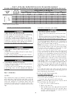
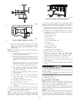
Fig. 54—Amp Draw Check With Ammeter

A96316

R

Y W G

10 TURNS

THERMOSTAT SUBBASE
TERMINALS WITH
THERMOSTAT REMOVED
(ANITICIPATOR, CLOCK, ETC.,
MUST BE OUT OF CIRCUIT.)

HOOK-AROUND
AMMETER

EXAMPLE:

5.0 AMPS ON AMMETER
10 TURNS AROUND JAWS


=  

0.5 AMPS FOR THERMOSTAT

     ANTICIPATOR SETTING

FROM UNIT 24-V
CONTROL TERMINALS

Table 10–GAS RATE (CU FT/HR)

SECONDS

FOR 1

REVOLUTION

SIZE OF TEST DIAL

SECONDS

FOR 1

REVOLUTION

SIZE OF TEST DIAL

1

Cu Ft

2

Cu Ft

5

Cu Ft

1

Cu Ft

2

Cu Ft

5

Cu Ft

10

360

720

1800

50

72

144

360

11

327

655

1636

51

71

141

355

12

300

600

1500

52

69

138

346

13

277

555

1385

53

68

136

340

14

257

514

1286

54

67

133

333

15

240

480

1200

55

65

131

327

16

225

450

1125

56

64

129

321

17

212

424

1059

57

63

126

316

18

200

400

1000

58

62

124

310

19

189

379

947

59

61

122

305

20

180

360

900

60

60

120

300

21

171

343

857

62

58

116

290

22

164

327

818

64

56

112

281

23

157

313

783

66

54

109

273

24

150

300

750

68

53

106

265

25

144

288

720

70

51

103

257

26

138

277

692

72

50

100

250

27

133

267

667

74

48

97

243

28

129

257

643

76

47

95

237

29

124

248

621

78

46

92

231

30

120

240

600

80

45

90

225

31

116

232

581

82

44

88

220

32

113

225

563

84

43

86

214

33

109

218

545

86

42

84

209

34

106

212

529

88

41

82

205

35

103

206

514

90

40

80

200

36

100

200

500

92

39

78

196

37

97

195

486

94

38

76

192

38

95

189

474

96

38

75

188

39

92

185

462

98

37

74

184

40

90

180

450

100

36

72

180

41

88

176

439

102

35

71

178

42

86

172

429

104

35

69

173

43

84

167

419

106

34

68

170

44

82

164

409

108

33

67

167

45

80

160

400

110

33

65

164

46

78

157

391

112

32

64

161

47

76

153

383

116

31

62

155

48

75

150

375

120

30

60

150

49

73

147

367

37

Summary of Contents for 311AAV Series 100

Page 1: ...ing in sensitive applications The 311AAV JAV furnace is approved for use with natural or propane gas and the 311JAV is also approved for use in Low NOx Air Quality Management Districts STANDARD FEATUR...

Page 2: ...Installation 10 Bottom Return Air Inlet 11 Horizontal Installation 12 Suspended Unit Support 12 Platform Unit Support 12 Roll Out Protection 12 Bottom Return Air Inlet 13 Side Return Air Inlet 13 Fil...

Page 3: ...ervice calls This is the safety alert symbol When you see this symbol on the furnace and in instructions or manuals be alert to the potential for personal injury Understand the signal words DANGER WAR...

Page 4: ...gn certified A Category I fan assisted furnace is an appliance equipped with an integral mechanical means to either draw or force products of combustion through the combustion chamber and or heat exch...

Page 5: ...ommun d autres appareils gaz MINIMUM INCHES CLEARANCE TO COMBUSTIBLE CONSTRUCTION Installation on non combusibible floors only For Installation on combustible flooring only when installed on special...

Page 6: ...recautions will help to avoid exposing the control to electrostatic discharge by putting the furnace the control and the person at the same electrostatic potential 1 Disconnect all power to the furnac...

Page 7: ...lvents such as perchloroethylene Printing inks paint removers varnishes etc Hydrochloric acid Cements and glues Antistatic fabric softeners for clothes dryers Masonry acid washing materials All fuel b...

Page 8: ...must be installed parallel with or on the downstream side of the unit to avoid condensation in the heat exchangers When installed parallel with the furnace dampers or other flow control must prevent...

Page 9: ...nace combustion air supply must be provided in accordance with this instruction manual The Standard Method 1 The space has no less volume than 50 cubic feet per 1 000 Btuh of the maximum input ratings...

Page 10: ...hin 12 300 mm of the floor The minimum dimension of air openings shall be at least 3 in 80 mm See Fig 8 c Combining space on different floor levels The volumes of spaces on different floor levels shal...

Page 11: ...m closure panel perform the following 1 Tilt or raise furnace and remove 2 screws holding bottom filler panel See Fig 9 2 Rotate bottom filler panel downward to release holding tabs 3 Remove bottom cl...

Page 12: ...lled in bottom return air opening Remove and discard this panel when bottom return air is used To remove bottom closure panel perform the following 1 Tilt or raise furnace and remove 2 screws holding...

Page 13: ...to joists The sheet metal MUST extend underneath the furnace casing by 1 in with the door removed The bottom closure panel on furnaces of widths 17 1 2 in and larger may be used for flame roll out pr...

Page 14: ...the design external static pressure The furnace airflow rates are provided in Table 5 AIR DELIVERY CFM With Filter When a furnace is installed so that the supply ducts carry air circulated by the furn...

Page 15: ...ply side air duct humidifier or other accesso ries All accessories MUST be connected to duct external to furnace casing Return Air Connections FIRE HAZARD Failure to follow this warning could cause a...

Page 16: ...CREWS IN SIDE AND 2 SCREWS IN BOTTOM Fig 17 Typical Attic Installation A03177 30 IN MIN WORK AREA 6 MIN TYPE B VENT 17 3 4 22 SHEET METAL SEDIMENT TRAP EQUIPMENT MANUAL SHUT OFF GAS VALVE LINE CONTACT...

Page 17: ...880 1715 2130 1995 1805 1645 2025 1895 1730 1565 1920 1785 1630 1480 1790 1675 1535 1390 1660 1565 1420 1280 1530 1420 1275 1145 1350 1260 1135 1005 Both Sides or 1 Side Bottom High Med High Med Low L...

Page 18: ...upstream of gas supply connection to furnace and downstream of manual equipment shutoff valve NOTE The furnace gas control valve inlet pressure tap connec tion is suitable to use as test gauge connect...

Page 19: ...A02075 Fig 18 Upflow Return Air Configurations and Restrictions A02163 Fig 19 Downflow Return Air Configurations and Restrictions A02162 Fig 20 Horizontal Return Air Configurations and Restrictions 18...

Page 20: ...rmitted by local code when installed in accordance with existing electrical codes Refer to the power cord manufacturer s ratings for proper wire gauge Do not use gas piping as an electrical ground FUR...

Page 21: ...Box Do not pinch wires between cover and bracket Electrical Box on Furnace Casing Side See Fig 23 FIRE OR ELECTRICAL SHOCK HAZARD Failure to follow this warning could result in personal injury death o...

Page 22: ...s between cover and bracket 24 V WIRING Make field 24 v connections at the 24 v terminal strip See Fig 23 Connect terminal Y Y2 as shown in Fig 24 for proper cooling operation Use only AWG No 18 color...

Page 23: ...NAL 24 VAC 0 5 AMP MAX TWINNING AND OR COMPONENT TEST TERMINAL BLOWER OFF DELAY Fig 25 Heating and Cooling Application Wiring Diagram with 1 Stage Thermostat A99440 115 V FIELD SUPPLIED DISCONNECT AUX...

Page 24: ...potential for vent gas leakage Category I furnaces operate with a flue loss not less than 17 percent to minimize the potential for condensation in the venting system These furnaces are approved for c...

Page 25: ...ed Air Conditioner A04216 See notes 2 5 8 and 10 on the page following these figures See notes 1 2 4 6 7 9 10 and 12 on the page following these figures A04217 Fig 28 Single Stage Furnace with Single...

Page 26: ...ingle Speed Heat Pump HUMIDFIER 24VAC See notes 1 2 3 4 11 12 and 14 on the page following these figures A04220 Fig 31 Dual Fuel Thermostat with Single Stage Furnace and Two Speed Heat Pump HUMIDFIER...

Page 27: ...default 7 Dip switch No 2 on Thermidistat should be set in ON position for two speed compressor operation 8 Configuration Option No 10 Dual Fuel Selection must be turned ON in all dual fuel applicati...

Page 28: ...ween the chimney and the metal liner APPLIANCE APPLICATION REQUIREMENTS Appliance operation has a significant impact on the performance of the venting system If the appliances are sized installed adju...

Page 29: ...lignment missing sections gaps Debris in cleanout Mortar tile metal vent fuel oil residue Is liner and top seal in good condition Is chimney property lined with clay tile liner Crown condition Missing...

Page 30: ...f flue extension is used fasten the flue extension to the vent elbow with at least two field supplied corrosion resistant sheet metal screws located 180 apart Fasten the vent connector to the flue ext...

Page 31: ...e page following these figures A03210 Fig 36 Downflow Application Vent Elbow Up then Left SEE NOTES 1 2 4 5 7 8 9 on the page following these figures A03211 Fig 37 Downflow Application Vent Elbow Up S...

Page 32: ...8 9 on the page following these figures A03215 Fig 42 Horizontal Left Application Vent Elbow Up SEE NOTES 1 2 4 5 7 8 9 on the page following these figures A03216 Fig 43 Horizontal Left Application Ve...

Page 33: ...al to the furnace 6 Accessory Downflow Vent Guard Kit KGAVG0101DFG required in downflow installations with lower vent configuration 7 Chimney Adapter Kit may be required for exterior masonry chimney a...

Page 34: ...nnections at the 24 v terminal block on the furnace control Failure to make proper connections will result in improper operation See Fig 25 3 Gas supply pressure to the furnace must be greater than 4...

Page 35: ...DO NOT redrill orifices Improper drilling burrs out of round holes etc can cause excessive burner noise and misdirection of burner flames This can result in flame impingement of heat exchangers causin...

Page 36: ...illed check orifice hole with a numbered drill bit of correct size Never redrill an orifice A burr free and squarely aligned orifice hole is essential for proper flame characteristics 4 Verify natural...

Page 37: ...late Recommended operation is at the mid point of rise range or slightly above 6 Set thermostat heat anticipator a Mechanical thermostat Set thermostat heat anticipator to match the amp draw of the el...

Page 38: ...ing the call for heat again i Furnace should ignite normally Step 5 Checklist 1 Put away tools and instruments Clean up debris 2 Verify that blower OFF DELAY time is selected as desired 3 Verify that...

Page 39: ...0 43 3 7 43 3 8 42 3 2 42 3 3 875 43 3 5 43 3 6 43 3 7 43 3 8 900 43 3 3 43 3 4 43 3 5 43 3 6 925 43 3 1 43 3 2 43 3 3 43 3 4 950 43 2 9 43 3 0 43 3 1 43 3 2 975 43 2 8 43 2 9 43 3 0 43 3 1 1000 43 2...

Page 40: ...3 3 0 43 3 1 43 3 2 750 43 2 7 43 2 8 43 2 9 43 3 0 775 43 2 6 43 2 7 43 2 7 43 2 8 800 43 2 4 43 2 5 43 2 6 43 2 7 825 43 2 3 43 2 3 43 2 4 43 2 5 850 43 2 1 43 2 2 43 2 3 43 2 4 ALTITUDE RANGE FT AV...

Page 41: ...nd flame sensing electrode The 24 v circuit contains an automotive type 3 amp fuse located on the control See Fig 24 Any shorts of the 24 v wiring during installation service or maintenance will cause...

Page 42: ...nifold Pressure Orifice No Manifold Pressure Orifice No Manifold Pressure U S A and Canada U S A Altitudes 2001 to 3000 or Canada Altitudes 2000 to 4500 800 43 3 8 42 3 2 42 3 3 42 3 4 825 43 3 5 43 3...

Page 43: ...3 2 8 43 2 9 43 2 9 750 43 2 5 43 2 6 43 2 7 43 2 8 775 43 2 3 43 2 4 43 2 5 43 2 6 800 43 2 2 43 2 3 43 2 3 43 2 4 825 43 2 1 43 2 1 43 2 2 43 2 3 850 48 3 7 43 2 0 43 2 1 43 2 1 ALTITUDE RANGE FT AV...

Page 44: ...call for heat R W closed or R W opens during blower on delay 13 LIMIT CIRCUIT LOCKOUT Lockout occurs if the limit draft safeguard flame rollout or blocked vent switch if used is open longer than 3 mi...

Page 45: ...k See Table 13 6 Slide filter into cabinet 7 Replace filter cabinet door 8 Turn on electrical supply to furnace BLOWER MOTOR AND WHEEL ELECTRICAL SHOCK HAZARD Failure to follow this warning could resu...

Page 46: ...cess door 20 Downflow or horizontal furnaces with vent pipe through furnace only a Install and connect short piece of vent pipe inside furnace to existing vent b Connect vent connector to vent elbow 2...

Page 47: ...optimum speed selection 10 Factory connected when BVSS Chimney Adapter Accessory Kit is not installed 11 Factory connected when LGPS is not used 12 Ignition lockout will occur after four consecutive...

Page 48: ...flange of collector box and attach to cell panel using existing screws making sure all screws are secure 13 Reconnect wires to the following components Use connec tion diagram on wiring label if wires...

Page 49: ...AC 1 will remain energized for 90 120 150 or 180 seconds depend ing on the blower OFF delay selection The furnace control CPU is factory set for a 120 second blower OFF delay 2 Cooling Mode The thermo...

Page 50: ...can be changed as many times as desired and is stored in the memory to be automatically used following a power interruption 5 Heat pump See Fig 28 31 for thermostat connections When installed with a h...

Page 51: ...ugh a brief component test sequence The inducer will start and run for the entire component test The HSI blower motor FAN speed AMBER LED boards only HEAT speed and COOL speed will run for 10 15 secon...

Page 52: ...combustion air supply flame rollout switch open Restricted vent Proper vent sizing Excessive wind 34 IGNITION PROVING FAILURE If flame is not sensed during the trial for ignition period the control wi...

Page 53: ...facturer reserves the right to discontinue or change at any time specifications or designs without notice and without incurring obligations Book 1 4 Tab 6a 8a PC 101 Catalog No See Cover Printed in U...

Reviews: