background image

Bandit

Copyright 12/07 

PAGE 117

MODELS 1290XP/1590 


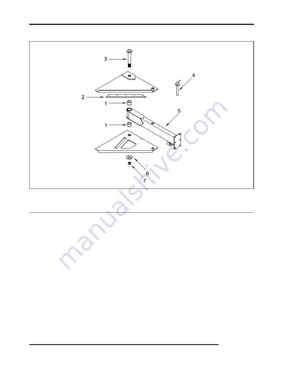
OPTIONAL COMPONENTS


MODEL 190

LOCATION 

PART NUMBER 

DESCRIPTION

1.   

900-1907-82 

Tension Bushing

2.   

911-1002-2 

Articulating Tongue Plastic Slide

.   

91-1017-16 

Articulating Tongue Pivot Pin

4.   

980-0500-16 

Articulating Tongue Lock Pin

.   

911-000-0 

Articulating Tongue Assembly

6.   

900-90-9 

Articulating Tongue Pivot Pin Washer

7.   

91-901-10 

Articulating Tongue Pivot Pin Nut

8.   

900-906-27 

Articulating Tongue Cylinder (Not Shown)

9  a. 

900-3920-01 

Articulating Tongue Valve (SAE O-Rings) (Not Shown)


b. 

900-3901-42 

Articulating Tongue Valve (Pipe Fittings) (Not Shown) 


MODEL 1590 ARTICULATING TONGUE

NOTE: Parts may not be exactly as shown.

Summary of Contents for 1290XP

Page 1: ...TRIES INC 6750 Millbrook Road REMUS MICHIGAN USA 49340 PHONE 800 952 0178 IN USA PHONE 989 561 2270 OR 561 2272 FAX 989 561 2273 SALES DEPT FAX 989 561 2962 PARTS SERVICE E MAIL www banditchippers com...

Page 2: ......

Page 3: ...ey and completely disconnect battery from cables wait for the chipper disc drum to come to a complete stop and to install the disc drum lock before performing any type of maintenance on the machine Al...

Page 4: ..._________________________________ 5 Did all welds appear to be of high quality _________________________________________________ 6 Was the overall machine to your liking ______________________________...

Page 5: ...Bandit Industries Inc Safety Booklet D A N G E R ACCIDENTS INVOLVING BRUSH CHIPPERS CAN AND SHOULD BE PREVENTED Operator training and enforcement of safety policies are ESSENTIAL...

Page 6: ...989 561 2270 Most if not all chipper related accidents are caused by operator negligence A lack of proper and ongoing training and lack of enforcement of safety policies significantly increase the op...

Page 7: ...Brush chippers are designed to be operated with hands placing the material into the chipper NOT FEET If the operator kicks the material that has become lodged or is not going into the feedwheels he o...

Page 8: ...rom your local Bandit dealer SAFETY FEATURE WOODEN PUSH PADDLE MOUNT Update Kit UK 1008 WOODEN PUSH PADDLE AND MOUNT 626 0000 52 14 Wide Paddle 980 0507 42 19 Wide Paddle 981 1005 30 22 Wide Paddle 98...

Page 9: ...padlocked SAFETY FEATURE SPRING LOCK FOR HOOD PIN Update Kit UK 1009 SPRING LOCK FOR HOOD PIN Since September 1998 mechanical feed hand fed Bandit Chippers have been built with a plug in device on the...

Page 10: ...tric parts The system typically consists of two simple cables hanging inside the infeed hopper and in front of the feedwheels approximately halfway between the entrance of the infeed hopper and the fe...

Page 11: ...he chipper must be familiar understand and follow instructions on the decals Decals are available in a variety of languages via Bandit dealers or factory Correct Installation and Care of Decals 1 You...

Page 12: ...eration In the long run sharp knives can save you money The chipper knives must be of good quality and the correct design for that model chipper The knives must be properly hardened at the edge anneal...

Page 13: ...er disc drum when someone else is working inside the chipper housing More than likely the chipper disc drum will turn hard then loosen causing it to turn faster If another person is anywhere near the...

Page 14: ...ent reminder as to the proper safe operation of any piece of equipment especially a chipper that is designed to quickly break down material much tougher than human flesh Please meet with your employee...

Page 15: ...S 76 CHIPPER COMPONENTS 82 CHIPPER KNIFE HARDWARE 86 ANVIL HARDWARE 87 DISCHARGE COMPONENTS 88 HYDRAULIC COMPONENTS 94 FRAME ACCESSORY COMPONENTS 104 FUEL HYDRAULIC TANK COMPONENTS 112 OPTIONAL COMPON...

Page 16: ...operating the product It is the responsibility of the owner or employer to insure that the operator is trained and practices safe operation while using and servicing the machine It is also the owner s...

Page 17: ......

Page 18: ...MBER AND OR WORK ORDER NUMBER LOCATIONS 1 Belt shield 2 W O on top of tongue 3 Side of frame other side of frame 4 Top of frame Note The engine information is located on the engine block The clutch in...

Page 19: ...ohol Keep children bystanders and animals clear of working area Never operate equipment that is in need of repair or adjustment Before starting the machine take a minute to check a few things The mach...

Page 20: ...rge chute before chipping Never stand in front of the chipper discharge chute Never direct the chute towards anyone or anything that could cause an accident or problems Always stop chipping and warn a...

Page 21: ...e DO NOT feed vines or vine like material DO NOT pile vines or vine like material in front of the infeed hopper which may cause you to trip or fall DO NOT allow vines or limbs to become entangled with...

Page 22: ...its instructions for operation service and adjustments Some styles require clutch engagement to be maintained so that it takes a lot of force others will require very little force and some are push b...

Page 23: ...th your fuel or fuel system supplier to ensure the delivery system is in compliance with fueling standards for proper grounding and bonding practices WARNING If the discharge or hood need to be remove...

Page 24: ...line The knives on the spinning disc drum can grab and pull in the winch line at a high rate of speed resulting in serious injury or death to workers nearby DANGER The winch line is under tension at t...

Page 25: ...chipper with the bottom clean out door in the open position because it subjects the door to physical abuse and damage during transportation This can damage the hinge and prevent the door from being p...

Page 26: ...eding into the chipper Never attach winch line to an installed choker if other limbs are feeding into the machine Brush can snag winch line or climbers ropes Knives can grab and pull in line and anyth...

Page 27: ...is will overwork the hydraulic system and make it difficult to feed larger material Always start the larger end base end of the log tree or branch into the feedwheel s first Keep the engine R P M s at...

Page 28: ...O NOT entangle feet or hands in undercarriage travel system DANGER NEVER sit stand lay climb or ride anywhere on this machine while it is running operating or in transit You will be injured DANGER Use...

Page 29: ...0 7000 to 7800 lbs 3175 to 3538 kg Approximate weights depending on engine and equipment options Overall Model 1290XP Height 96 2 4 m Length 208 5 3 m Width 85 2 2 m Dimension Model 1590 Height 107 2...

Page 30: ...DECALS DECAL LOCATIONS MODEL 1290XP Decal locations may vary these are general locations 2 16 23 12 42 31 46 47 21 2 22 11 44 12 36 48 13 22 45 6 8 32 33 34 25 16 27 28 35 37 39 40 41 4 7 38 3 18 24 4...

Page 31: ...o Check Torque 14 INST 02 Yoke Lock Hole 15 INST 03 Yoke Lock Bar 16 INST 04 Arrow 17 INST 05 Yoke Lift Up Down 18 INST 07 Discharge Swivel Right Left 19 INST 08 Winch Control Out In 20 INST 09 Select...

Page 32: ...DECALS DECAL LOCATIONS MODEL 1290XP Decal locations may vary these are general locations 2 16 23 12 42 31 46 47 21 2 22 11 44 12 36 48 13 22 45 6 8 32 33 34 25 16 27 28 35 37 39 40 41 4 7 38 3 18 24 4...

Page 33: ...Personal Protection 50 SPW 10 Hydraulic Winch 51 900 8900 30 Basic Safety Decal Kit Options may require additional decals 52 900 8900 21 Bandit Model 1290XP Logo Decal Kit Additional Decals for Machin...

Page 34: ...ECALS DECAL LOCATIONS MODEL 1590 Decal locations may vary these are general locations 37 49 11 45 13 22 2 16 2 22 46 6 8 33 12 43 12 32 2 16 23 1 51 3 18 25 44 50 26 27 28 29 36 38 40 41 42 34 35 4 7...

Page 35: ...2 ID 42 Bandit Industries Inc USA 13 INST 01 Remove To Check Torque 14 INST 02 Yoke Lock Hole 15 INST 03 Yoke Lock Bar 16 INST 04 Arrow 17 INST 05 Yoke Lift Up Down 18 INST 07 Discharge Swivel Right L...

Page 36: ...ECALS DECAL LOCATIONS MODEL 1590 Decal locations may vary these are general locations 37 49 11 45 13 22 2 16 2 22 46 6 8 33 12 43 12 32 2 16 23 1 51 3 18 25 44 50 26 27 28 29 36 38 40 41 42 34 35 4 7...

Page 37: ...Personal Protection 51 SPW 10 Hydraulic Winch 52 900 8900 30 Basic Safety Decal Kit Options may require additional decals 53 900 8900 23 Bandit Model 1590 Logo Decal Kit Additional Decals for Machine...

Page 38: ...nt with a decal attached be sure and replace the decal 4 Replacement decals are available and can be purchased from the manufacturer or your Bandit Dealer 5 Combination English Spanish decals are typi...

Page 39: ...Bandit Copyright 12 07 PAGE 23 MODELS 1290XP 1590 DECALS...

Page 40: ...Bandit Copyright 12 07 PAGE 24 MODELS 1290XP 1590 DECALS...

Page 41: ...eed on to resume forward travel Due to required components and equipment options a machine may have various types or brands of autofeed systems Each chipper is shipped with the original manufacturer s...

Page 42: ...machines it will have a connector with a light screwed to it When the solenoid is activated indicated by the light in the connector the feedwheel s are reversed by the autofeed plus system See Figure...

Page 43: ...oid and or cartridge Check fuse on dump valve signal wire if equipped Checkcontinuityonthedumpvalvewire normallygreenwire Check autofeed tachometer settings Check autofeed tachometer settings Check fo...

Page 44: ...50 2150 2150 2400 2400 2150 2150 2050 2400 2400 2200 2150 2050 1900 1900 2050 2150 2150 Magnetic Pick Up PPR 126 126 126 126 110 127 159 159 N A N A 30 129 129 30 30 N A 126 126 126 126 126 126 159 Fe...

Page 45: ...THE 1 JAM NUT TO ADJUST CONTROL HANDLE PIVOT TENSION PUSH TO REVERSE FEEDING ADJUST PIVOT TENSION WITH THE TIGHTNESS OF INSIDE FRICTION NUTS SECURE ADJUSTMENT WITH OUTSIDE JAM NUTS ADJUSTING TENSION F...

Page 46: ...4 Motor Coupler 5 Infeed Hopper 6 Folding Infeed Pan 7 Feedwheel Control Bar 8 Hydraulic Control Valves 9 Hydraulic Winch Area Optional 10 Wooden Push Paddle 11 Yoke Lift Cylinder Optional 12 Knives...

Page 47: ...the operator To make the winch pull material in pull the winch control handle out towards the operator The winch also has a spool rotation lock make sure this is disengaged to free wheel cable out of...

Page 48: ...aware of the hazards of winch line breakage Ensure that everyone remains clear of the recoil area in the event of load or cable breakage Pull loads in a manner that avoids angles which could result in...

Page 49: ...ine securely to the wood material that you want pulled to the chipper 5 Engage the winch by pulling the actuator handle out and turning it 90 If the machine has the winch control panel position the sw...

Page 50: ...ch is disengaged and pull the cable to the material to be reeled in Attach cable securely to the wood material that you want pulled to the chipper 5 Make sure everyone is clear and then retract the cl...

Page 51: ...e plug becomes disconnected while the chipper engine is running the engine will be shut down or be disabled from running This is for safety purposes to ensure that the hood pin is not removed and the...

Page 52: ...engines may have a choke adjustment pull the choke lever out to choke the engine Push the choke lever in for normal engine operations 5 Throttle Adjustment if equipped Some engines may have a knob or...

Page 53: ...transporting the machine Also check brakes if equipped to make sure they are operating correctly 14 Do not transport unless discharge is clamped pinned and bolted securely into place in the transport...

Page 54: ...ADING OR UNLOADING THE MACHINE INSPECT AND CONFIRM THE FOLLOWING STEPS When loading or unloading the self propelled machine on the trailer use care and caution The maneuvering of the equipment must be...

Page 55: ...d preventative maintenance program you should have years of trouble free operation Before attempting any type of maintenance disengage clutch turn off engine wait for the disc drum to come to a comple...

Page 56: ...chipper drum assembly Check for the condition of knife bolt threads secure welds torqued bolts excessive wear and impact cracks If a problem is found contact the chipper manufacturer or an authorized...

Page 57: ...m video 29 Make sure all safety equipment is being worn Hard hat gloves eye protection ear protection etc 30 RemembertocheckEVERYTHINGonthe checklist 21 Check air cleaner or precleaner Clean or replac...

Page 58: ...e direction adjustor build up repair or replace as needed 3 Inspect feedwheel motor connections Check and maintain correct torque on feedwheel motor connections See page 48 4 Check feedwheel teeth for...

Page 59: ...CHART THESE TORQUES ARE BASED ON DRY CLEAN THREADS DESCRIPTION BOLT SIZE TORQUE FT LBS TORQUE Nm Before tightening bolts be sure you have the correct size bolt for the correct amount of torque Use on...

Page 60: ...talled correctly 12 Grease chipper bearings purge and feedwheel bearings 1 shot daily 13 Check and or adjust belt tension on chipper and hydraulic pump belt drives 14 Check hydraulic pump and motor sh...

Page 61: ...Check hydraulic function pressures Set to specified PSI bar 8 Check and grease or oil wheel bearings follow axle MFG instructions 9 Check and adjust brakes follow axle MFG instructions 10 Lubricate Ba...

Page 62: ...orrect torque on the opposite side of the engine from the engine adjusters 6 Loosen the jam nuts on the engine adjuster on the radiator end of the engine 7 Torque the engine mount bolt and then tighte...

Page 63: ...BELT BELT SHEAVE SHEAVE SHEAVE BELT Main Drive belts maximum of 3 8 deflection with 22 to 24 lbs of force Pump Drive belts maximum of 1 4 deflection with 12 lbs of force SPACE MAINTENANCE SECTION BEL...

Page 64: ...adjusting spring tension have the top feedwheel in the lowered position Use the Clevis Pin with Clip to adjust the tension Make sure that the Clevis Pin is installed properly and that the Clip is secu...

Page 65: ...to be adjusted closer to the drum loosen the outside hex nuts If the anvil needs to be adjusted away from the drum loosen the inside hex nuts Next loosen the anvil clamp bolts from underneath the mac...

Page 66: ...ce that knife has been checked very carefully rotate the chipper drum so the other knives can be checked 6 Once all knives have been checked adjust the cable rope shear according to the closest knife...

Page 67: ...on DANGER cable rope shear COUNTER KNIFE REPLACEMENT 1 To replace the cable rope shear counter knife first remove the cable rope shear adjustment cover on either side of the drum housing 2 Remove the...

Page 68: ...nock out the pin You may have to run impact on bolt and hit with hammer a few times to remove pin Do not spend excessive time trying to remove the pin and coupler If problems occur during pin and coup...

Page 69: ...1 more pass torquing the locking screws to 52 ft lbs 71 Nm No screws should turn at this point or repeat step 7 C Removal Procedure 1 Make sure there are no torque or thrust loads on the coupler feedw...

Page 70: ......

Page 71: ...ris use a degreaser 2 Install both feedwheel bearings on the feedwheel shaft with the Grip Tight bearing on the hydraulic motor side and the set screw bearing on the opposite side Do not lock the bear...

Page 72: ...slightly until one of the slots line up 7 Offset the bearing on the curb side of the machine about 1 8 3 2 mm to 3 16 4 8 mm away from the drum housing so that when the bearing is tightened up on the...

Page 73: ...the chute Then two people must remove the chute Do not attempt this with one person because the chute can fall causing injury If used properly a hoist can be used to assist in the removal of the chute...

Page 74: ...ely Simply sand the edges of the damaged paint area mask off the surrounding area and apply primer and paint to the dry clean and warm surface This will help keep the damaged area from spreading or ge...

Page 75: ...will be set up initially from our factory to assure proper operation during the normal break in period No further adjustment will be necessary until the vehicle completes the recommended break in per...

Page 76: ...ing the wide temperature swings of spring and fall To find the closest Petro Canada Hydrex XV dealer call 1 888 284 4572 Multi Viscosity motor oils not recommended to mix with Petro Canada Hydrex XV h...

Page 77: ...peration The actual viscosity needed is based on oil temperature during operation and not air temperature Compare your fluid specifications with the specifications below to verify compliance When choo...

Page 78: ...p Relief PSI bar Yoke Down Relief PSI bar Winch Relief PSI bar Disch Rotate PSI bar Disch Flipper PSI bar Front Stab PSI bar 1290XP Starting S N 7071 10 2 38 6 5 1 19 3 5 1 19 3 32 35 2500 172 2500 17...

Page 79: ...y be located in the relief valve or something as simple as belts slipping check these first Only use the optional adjustable flow control when chipping large diameter trees Do not leave the speed adju...

Page 80: ...y open which weakens the feedwheel power The relief as well as hydraulic oil and screen must be kept clean 1 VALVE SEAT The springs pushes the relief valve ball against it until pressure builds 2 POPP...

Page 81: ...rrectly 1 First put control handle in off position 2 Disconnect flow divider from control valve and plug port on flow divider 3 Leave all other hydraulic hoses connected 4 Install pressure gauge in po...

Page 82: ...ust engine to full throttle to activate reading on pressure gauge 5 Pressure gauge should read maximum 2500 PSI 172 bar ONLY RUN ENGINE FOR 4 5 SECONDS TO SET PRESSURE OR YOU MAY DAMAGE HYDRAULICS 6 L...

Page 83: ...put control handle in off position 2 Disconnect hose coming out of the port farthest from the handle of the control valve from the optional motor or cylinder and plug the hose 3 Leave all other hydrau...

Page 84: ...or replace feeding 3 Pump is worn 3 Replace 4 Motor is worn 4 Replace 5 Feedwheel springs too tight 5 Adjust 6 Feedwheel slide box sticking or 6 Lubricate hanging up Feedwheel s turn 1 Relief valve st...

Page 85: ...hydraulic pressure adjustment procedure section of the valve setting manual to find the correct procedure for checking relief valve setting pgs 58 61 Adjusting relief Refer to the hydraulic pressure a...

Page 86: ...he pump the clutch may have to be engaged if the pump is belt driven 8 Have a second person lift the hydraulic hose far enough out of the tank inlet to observe the flow of oil going into the tank Obse...

Page 87: ...e gauge reading to make sure a high pressure does not exist 8 Increase the engine speed slowly to full rpm and at the same time observe the pressure and flow rate The pressure should still remain low...

Page 88: ...hydraulic motor back to the control valve at the valve Some machines will be equipped with a flow divider between the hydraulic motor and the control valve 4 Place the end of the hose in a clean 5 gal...

Page 89: ...g area free of debris and shop rags 3 16 Tee handle hex driver 1 2 drag link drive socket jawed vice General Procedure Disassembly 1 Secure valve in vice or suitable method to firmly hold valve 2 Note...

Page 90: ...8 MODELS 1290XP 1590 SPECIFIC SCHEMATIC FUNCTION MAY VARY DEPENDING ON OPTIONS OR COMPONENT MANUFACTURE WITH NO OPTIONS FEEDWHEEL MOTOR HYDRAULIC SECTION FEEDWHEEL MOTOR FLOW DIVIDER CONTROL VALVE PUM...

Page 91: ...G ON OPTIONS OR COMPONENT MANUFACTURE WITH AUTOFEED PLUS YOKE LIFT CYLINDER AND WINCH HYDRAULIC SECTION FEEDWHEEL MOTOR FEEDWHEEL MOTOR FLOW DIVIDER CONTROL VALVE PUMP SUCTION SCREEN TANK FILTER CONTR...

Page 92: ...with EP 2 Lithium type grease B Chipper drum operating at too high RPM s DO NOT exceed recommended RPM s C Bearings worn out REPLACE D Bearing locknut is loose 1 Chipper Makes Poor Quality Chips or D...

Page 93: ...ounting hardware and torque knife mounting hardware to the specified torque Replace knife mounting hardware after 5 times of tightening KNIFE GRINDING AND FILING NOTICE Many times a chipper knives cut...

Page 94: ...secure welds excessive wear impact cracks and elongated bolt holes on disc chippers or the condition of the knife bolt threads on drum chippers If a problem is found contact your local dealer or Bandi...

Page 95: ...um type grease only for all bearings Purge chipper bearings with grease you can not over grease these bearings Grease feedwheel bearings with one shot of grease Both types of bearings are designed wit...

Page 96: ...ES BLACK LEFT TURN YELLOW OLD STYLE 6 Wire Main Cable Color Code Black BL Brakes White W Ground Green G Right Turn Yellow Y Left Turn Brown BR Running Lights Red R Breakaway Switch WIRING FOR STANDARD...

Page 97: ...Inc reserves the right to make changes in models size design installations and applications on any part without notification All nuts bolts washers and many other components can be ordered by physical...

Page 98: ...Bandit Copyright 12 07 PAGE 76 MODELS 1290XP 1590 INFEED HOPPER COMPONENTS NOTE Parts may not be exactly as shown 59 MODEL 1590 Infeed Hopper Cover...

Page 99: ...200177 Tail Light Mount Curb Side 16 a 900 2908 76 900 2908 76 LED Tail Light b 900 2908 74 900 2908 74 Adapter Wire for LED Tail Light Not Shown 17 900 2908 75 900 2908 75 Rubber Grommet for LED Tai...

Page 100: ...Bandit Copyright 12 07 PAGE 78 MODELS 1290XP 1590 NOTE Parts may not be exactly as shown INFEED HOPPER COMPONENTS NOTE Parts may not be exactly as shown 59 MODEL 1590 Infeed Hopper Cover...

Page 101: ...49 981 100049 Top Torque Arm With Coupler Guard Mount Start 4 06 b 981 300197 981 300197 Top Feedwheel Torque Arm Start 4 06 c 981 1006 44 N A Top Feedwheel Torque Arm Pre 4 06 d N A 981 1006 44 Top F...

Page 102: ...Bandit Copyright 12 07 PAGE 80 MODELS 1290XP 1590 NOTE Parts may not be exactly as shown INFEED HOPPER COMPONENTS NOTE Parts may not be exactly as shown 59 MODEL 1590 Infeed Hopper Cover...

Page 103: ...ottom Feedwheel Assembly Start 12 05 c N A 914 0502 52 Bottom Feedwheel Assembly Pre 12 05 d 955 1001 52 955 1001 52 Bottom Feedwheel Tooth e 955 0500 46 955 0500 46 Bottom Feedwheel Shaft Coupler Ass...

Page 104: ...Bandit Copyright 12 07 PAGE 82 MODELS 1290XP 1590 CHIPPER COMPONENTS NOTE Parts may not be exactly as shown OLD STYLE PRE 2 04...

Page 105: ...e Loop Crimp Sleeves 12 a 900 1905 97 900 1905 97 Chipper Drum Bearing b 900 4910 40 900 4910 40 Chipper Drum Bearing Bolt Road Side Only Not Shown c 900 4910 34 900 4910 34 Chipper Drum Bearing Bolt...

Page 106: ...Bandit Copyright 12 07 PAGE 84 MODELS 1290XP 1590 CHIPPER COMPONENTS NOTE Parts may not be exactly as shown OLD STYLE PRE 2 04...

Page 107: ...Drum Head Shaft 34 a 911 100000 911 100000 Hood Pin With Attaching Chain b 900 4902 20 900 4902 20 Padlock For Hood Pin Not Shown c P812 P812 Key For Padlock Not Shown 35 a 955 1003 94 955 1003 94 Dru...

Page 108: ...fe Bolt NOTE Torque Knife Bolts to 180 ft lbs 245 Nm KNIFE BOLTS MUST BE INSTALLED THROUGH KNIFE AS SHOWN Part Numbers For Models 1290XP 1590 Knives LOCATION PART NUMBER DESCRIPTION 4 900 9901 68 Knif...

Page 109: ...x 4 1 2 Current b 900 4902 73 Anvil Eye Bolt 1 2 13NC x 5 1 2 Prior 5 900 4902 11 1 2 Lock Washer 6 900 4903 17 1 2 13NC x 2 1 2 Hex Head Bolt 7 900 4900 45 1 2 13NC Hex Nut 8 900 4900 74 1 2 13NC x 2...

Page 110: ...12 Discharge Flipper Assembly b 937 0502 24 12 Enclosed Discharge Flipper Assembly c 937 0501 63 12 Enclosed Discharge Flipper Assembly For Hydraulic Flipper 4 900 4901 83 Discharge Flipper Adjusting...

Page 111: ...ank Adj Height Hinge Assembly Includes s 6 8 9 937 0501 65 Straight Section Hand Crank Adj Height Discharge 10 981 1001 63 Discharge Flipper Hinge 11 a 937 1009 10 12 Discharge Flipper Assembly b 937...

Page 112: ...ket For Hydraulic Motor 7 980 0110 63 Sprocket For Discharge Weld On 8 900 4905 00 Spacer Washer 9 980 0122 18 Bottom Swivel Ring 10 937 1004 30 Hydraulic Swivel Motor Mount 11 981 1001 63 Discharge F...

Page 113: ...0006 42 Straight Section Cylinder Lug 4 981 1001 63 Hydraulic Flipper Hinge 5 980 0126 48 Flipper Lug 6 937 0501 63 12 Hydraulic Flipper Assembly Enclosed 7 900 3930 71 Cylinder Lug Pin 3 4 Dia x 2 1...

Page 114: ...Bandit Copyright 12 07 PAGE 92 MODELS 1290XP 1590 DISCHARGE COMPONENTS HAND CRANK SWIVEL DISCHARGE NOTE Parts may not be exactly as shown...

Page 115: ...8 74 50 Roller Chain b 900 1901 18 Half Link Chain Not Shown c 900 1901 19 Master Link Chain Not Shown 10 980 0127 32 Sprocket For Hand Crank Swivel Discharge Weld On 11 980 0137 35 Spacers Blocks 12...

Page 116: ...07 PAGE 94 MODELS 1290XP 1590 HYDRAULIC COMPONENTS NOTE Parts may not be exactly as shown TYPICAL MODELS 1290XP 1590 HYDRAULIC SCHEMATIC With No Options Examples of straight fittings PIPE FITTING JIC...

Page 117: ...lic Motor Model 1590 Start 12 05 c N A 900 3908 67 Bottom Feedwheel Hydraulic Motor Model 1590 Pre 12 05 8 a N A 900 3908 67 Top Feedwheel Hydraulic Motor Model 1290XP b N A 900 3908 67 Top Feedwheel...

Page 118: ...C With Options NOTE Parts may not be exactly as shown Examples of straight fittings PIPE FITTING JIC SAE O RING 1 1 12 2 16 To Yoke Lift From Hydraulic Pump 6 18 9 10 19 2 1 8 12 11 1 1 17 1 16 20 21...

Page 119: ...t b 900 3908 62 900 3920 09 Yoke Lift Control Valve With Winch Option Model 1290XP c 900 3901 24 900 3920 02 Yoke Lift Control Valve Without Winch Option Model 1290XP d 900 3908 62 900 3920 09 Yoke Li...

Page 120: ...EM SINGLE SOLENOID Torque Retainer Nut to a Maximum of 4 to 6 ft lbs 5 to 8 Nm and Install Vibra Tite Over Torque Will Cause Damage and Will Also Void Warranty Torque Autofeed Cartridge Nut to a Maxim...

Page 121: ...y Used Without Autofeed AUTO FEED PLUS SYSTEM SINGLE SOLENOID LOCATION PART NUMBER DESCRIPTION 1 a 900 3915 19 Retainer Nut Northman b 900 3920 20 Retainer Nut and Sealing Ring Danfoss 2 900 2909 55...

Page 122: ...Bandit Copyright 12 07 PAGE 100 MODELS 1290XP 1590 HYDRAULIC COMPONENTS HOSE CLAMP NOTE Parts may not be exactly as shown HOSE GUARD FLOW DIVIDER...

Page 123: ...3 4 Double Clamp Assembly Includes s 1 4 i 900 3914 04 1 Single Clamp Assembly Includes s 1 4 j 900 3914 05 1 1 4 Single Clamp Assembly Includes s 1 4 k 900 3914 06 1 1 2 Single Clamp Assembly Include...

Page 124: ...102 MODELS 1290XP 1590 HYDRAULIC COMPONENTS NOTE Parts may not be exactly as shown 11 9 8 4 12 6 6 7 2 1 12 3 12 6 6 7 10 1 2 3 4 6 7 8 9 10 11 12 13 6 6 6 7 9 TYPICAL FEEDWHEEL CONTROL VALVES TYPICAL...

Page 125: ...r Control Valve NOTE NOT INCLUDED IN SEAL KIT 8 900 3901 12 Relief Valve Kit Spring Ball Screw NOTE SOLD ONLY AS A KIT 9 904 0003 34 Valve Spool Stop For Spring Loaded Valve 10 904 0003 35 Valve Spool...

Page 126: ...Bandit Copyright 12 07 PAGE 104 MODELS 1290XP 1590 MODEL 1290XP FRAME ACCESSORY COMPONENTS NOTE Parts may not be exactly as shown...

Page 127: ...7237 c 900 5903 78 8 000 Lbs Drop Leg Jack Optional 13 980 300106 Trailer Plug Receptacle Mount 14 980 0121 31 Safety Chain Holder 15 a 900 4912 71 Safety Chain W Hooks and Spring Latches for Standar...

Page 128: ...Bandit Copyright 12 07 PAGE 106 MODELS 1290XP 1590 MODEL 1290XP FRAME ACCESSORY COMPONENTS NOTE Parts may not be exactly as shown...

Page 129: ...2 0501 16 Telescopic Tongue Assembly 26 a 980 0508 25 Optional Wheel Chock Holders Aluminum Bolt On Not Shown b 980 0508 26 Optional Wheel Chock Holders Metal Weld On Not Shown 27 900 5902 32 Optional...

Page 130: ...Bandit Copyright 12 07 PAGE 108 MODELS 1290XP 1590 MODEL 1590 FRAME ACCESSORY COMPONENTS NOTE Parts may not be exactly as shown...

Page 131: ...80 0509 37 Steel Battery Box For 660 CCA Battery And Manual Holder c 914 0501 46 Steel Battery Box For 1400 CCA Battery And Manual Holder Cummins Tier 3 15 900 9902 07 Manual Holder 16 900 7900 08 Pla...

Page 132: ...Bandit Copyright 12 07 PAGE 110 MODELS 1290XP 1590 MODEL 1590 FRAME ACCESSORY COMPONENTS NOTE Parts may not be exactly as shown...

Page 133: ...e Only Pre 8 06 f 900 5904 22 16 x 6 White Spoke 8 Bolt Rim Only Pre 8 06 28 Brake Hub and Drum Assembly 29 981 0501 18 Telescopic Tongue Assembly 30 a 980 0508 25 Optional Wheel Chock Holders Aluminu...

Page 134: ...Sight Gauge For 12 Gallon Hydraulic Tank Start S N 7111 5 05 5 900 3922 60 Magnetic Drain Plug 6 a 912 200011 24 1 2 Gallon Fuel Tank 12 Gallon Hydraulic Tank Mount b 900 0104 95 Rubber Fuel Tank Pad...

Page 135: ...22 60 Magnetic Drain Plug 6 a 911 200014 30 Gallon Fuel Tank 12 Gallon Hydraulic Tank Mount Start 12 05 b 900 0104 95 Rubber Fuel Tank Pad Not Shown 7 911 200013 30 Gallon Fuel Tank Assembly Start 12...

Page 136: ...ch Brake Shoe Only 10 40024 Winch Spring 11 a 40469 Winch Shift Lever Only b 900 3905 16 Winch Shift Lever With s 9 10 12 a 40025 Winch Pin For Brake Assembly b 41669 Winch Snap Ring For Winch Pin 13...

Page 137: ...ylinder Tie Rod c 904 0007 14 Pin For Welded Cylinder Not Shown 2 914 1000 38 Lock Pin 3 980 0131 50 Inside Tube Assembly 4 980 0509 53 Drop Leg Foot Pad Assembly 5 900 3925 94 Check Valve 6 a 900 392...

Page 138: ...ck Tab Foldaway Radiator Screen 3 Mount Tray For Foldaway Radiator Screen 4 900 7900 57 Weather Strip 5 a 900 4901 83 Spring Lock Plunger b 900 7900 93 Rubber Cap For Spring Lock 1 2 Diameter 6 900 49...

Page 139: ...4 980 0500 16 Articulating Tongue Lock Pin 5 911 0500 40 Articulating Tongue Assembly 6 900 4905 95 Articulating Tongue Pivot Pin Washer 7 914 4901 10 Articulating Tongue Pivot Pin Nut 8 900 3906 27...

Page 140: ...Bandit Copyright 12 07 PAGE 118 MODELS 1290XP 1590 SERVICE RECORD SERVICE RECORD DATE DESCRIPTION AMOUNT...

Reviews: