IntelliGear Plus
TM
Variable Speed Gearmotors and Motors
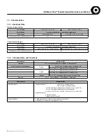
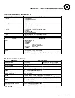
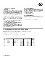
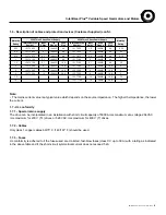
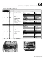
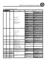
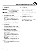
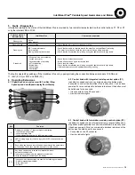
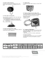
3.2 - Control Terminal Blocks (cont'd.)
Terminal Number
Designation
Function
Characteristics
IntelliGear Frame
31 or 32
33
Characteristics
Analog voltage (common
Mode) or uni-directional
Voltage input
Full scale voltage
10 V ± 2%
Input impedance
95 kΩ
Current input
Current range
0 to 20 mA ± 5%
Analog or logic input or
Input impedance
500 Ω
analog output 3
Resolution
10 bits
Sampling
6 ms
6
6
ADIO3
Assignment in standard
Logic input (if connected to the +24 V
configuration:
Threshholds
“0”:<5V-”1”; >10V
Voltage range
0 to +24V
analog output
Load
95 kΩ
(LED control option for frame
Input threshold
7.5V
33 and speed feedback for
Voltage output
frames 31 and 32)
Voltage range
0 to 10V
Load resistance (min.)
2 kΩ
Protection
Short-circuit (40mA max.)
Current output (Frame 33 ONLY)
Current range
0 to 20 mA + 5%
Maximum voltage
10 V
Load resistance
500 Ω
Characteristics
Digital input or output 1
Threshholds
“0”:<5V-”1”; >10V
Voltage range
0 to +24V
Digital input or output 1
Sampling/refreshment
2 ms
Digital input
Assignment in standard
Absolute maximum voltage
0 to +35V
7
7
DIO1
configuration:
Load
15 kΩ
Input threshold
7.5V
digital input
Logic input
External fault interlock
Maximum output current
50 mA
Overload current
50 mA
Output current
10 mA in total
5
8
Overload current
33 = 150mA, 31/32 = 50mA
24V
+24V internal source
Accuracy
± 5%
11
11
Protection
Current limiting and overload
fault trip
Logic input 2
Characteristics
Logic input (positive logic)
8
9
DI2
Assignment in standard
Threshold
“0”:<5V-”1”; >10V
configuration: Run forward
Voltage range
0 to +24V
Logic input 3
Sampling/refreshment
2 ms
9
10
DI3
Assignment in standard
Absolute maximum voltage
0 to +35V
configuration: Run reverse
range
Logic input 4
10
12
DI4
Assignment in standard
Load
15 kΩ
Configuration: Selection of
0-10 VDC or 4-20 mA analog ref.
for ADI1 (4-20mA is selected by
Input threshold
7.5V
a +24V Input)
Characteristics
Logic input (positive logic)
N/A
13
SDI1
+24V dedicated to safety input
Thresholds
“0”:<5V-”1”; >18V
Voltage range
9 to + 35V
12
14
SDI2/ENA
Safety/unlocking input
Impedance
820 Ω
33: NO-NC single pole
13
15
COM/RL1
Characteristics
changeover contact
N/A
16
RL1C
Fault relay output
31/32: NO single pole contact
14
17
RL1O/RL2
250VAC maximum contact
-4 A, resistive load
current
-2 A inductive load
Characteristics
NO single-pole changeover
N/A
18
SDO1
Safety contact
contacts
19
250VAC maximum contact
-4 A, resistive load
N/A
N/A
SDO2
current
-2 A inductive load
14
MCIM15100E • Form 9112E • Printed in USA


