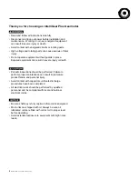
IntelliGear Plus
TM
Variable Speed Gearmotors and Motors
TX-10
TX-20
2 - Installation
It is the responsibility of the owner or user
to ensure that the installation, operation and maintenance
of the inverter and its options comply with legislation relating
to the safety of personnel, animals and equipment, and with
the current regulations of the country of use.
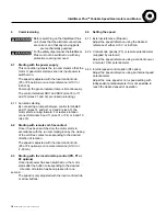
• Before carrying out any work, disconnect and lock the drive
power supply. For the single-phase range, wait two minutes
to make sure that the capacitors have discharged.
• After connection, ensure that the seals are firmly in place,
and that the screws and cable glands are watertight to ensure
drive protection. Clear any condensation from the drain holes
at the bottom of the motor.
2.1 - General
The
I
ntelliGear Plus is usually fitted to the gear and mounted
to the machine with flange or foot mounting.
The motor fan cools the whole assembly. Make sure that
the ventilation air inlet is free of obstruction.
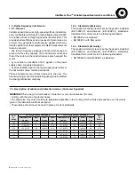
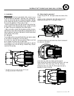
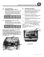
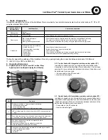
The positions of the potentiometer/cable gland supports
are specified at the time of ordering. However they may be
reversed if necessary.
4. Reverse the option and cable gland supports.
5. Reconnect the printed circuit plug connector on P2 and
replace the TX 10 screws using .5 ft.-lbs. of torque.
6. Replace the cover using TX-20 slot type screws by
applying 3 ft.-lbs. of torque.
3. Disconnect the plug connector from the P2 terminal if
an option is connected.
2.2 - Reversing the operators*
1. Undo the (2) TX 20 - slot type screws and remove the
cover.
2. Remove the control knob and cable gland support
attachment screws (TX10 - slot type screws).
* If IntelliGear Plus unit is equipped with an FCR brake,
reversing potentiometer is not permitted.
MCIM15100E • Form 9112E • Printed in USA
11


