29
II-
9.2.1.4. LCD Check Display
Here, check for missing dots and the display function of the LCD.
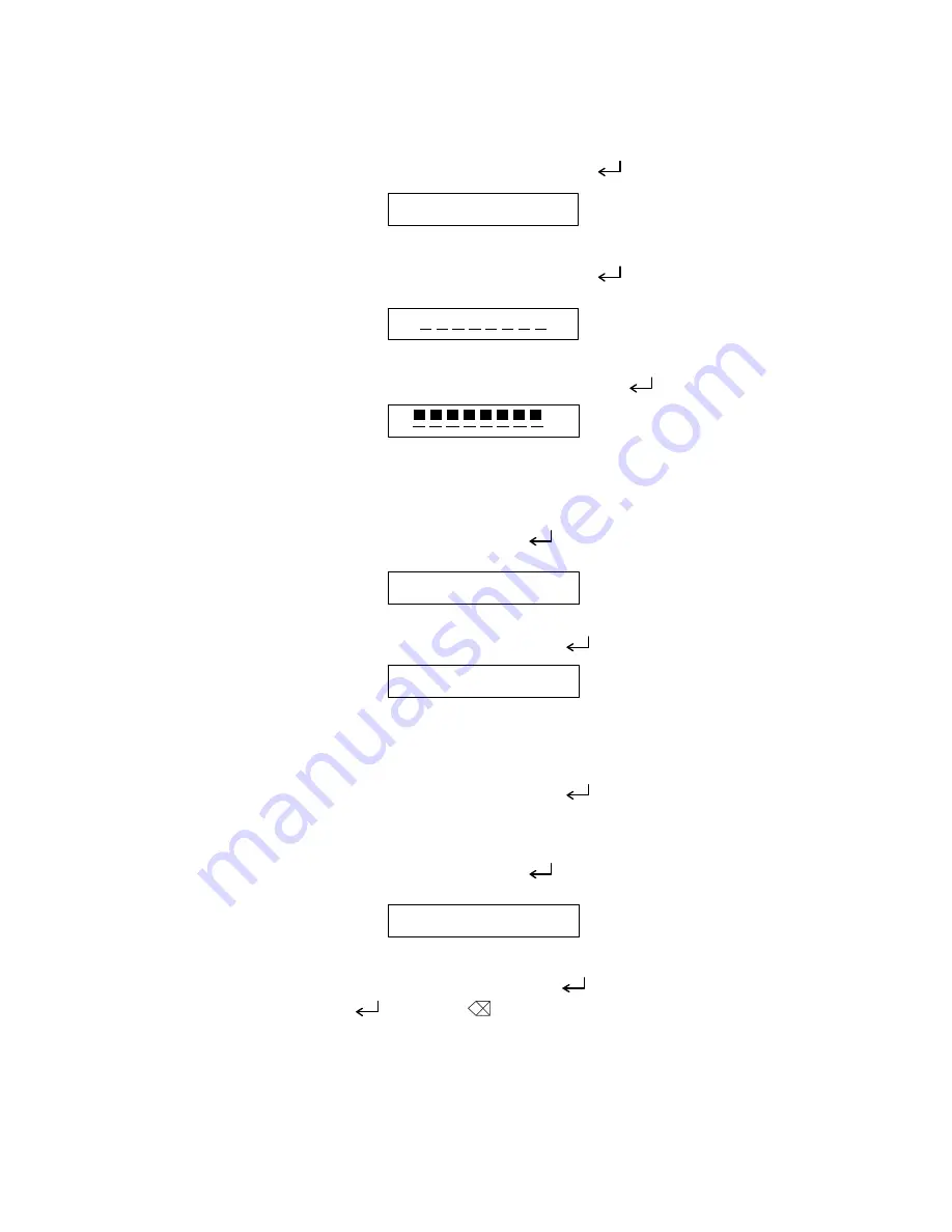
The LCD check 1 <Fig. 4> is displayed when depressed “ ” key.
Fig. 4
The LCD check 2 <Fig. 5> is displayed when depressed “ ” key.
Fig. 5
Shifts to “28.2.2 Cassette Inspection Mode” when depressed “ ” key. (Fig. 7 Display)
Fig. 6
9.2.2. Cassette Sensor Inspection Mode “2” Key
Here, ckeck the cassette sensor function.
Display of Fig. 7 is indicated when depressed “ ” key or depressed “2” key in the display
of Fig. 6 (except while in the Key Inspection Mode).
Fig. 7
Shifts to the Key Inspection Mode when depressed “ ” key. (Fig. 8 Display)
Fig. 8
Displays the three sensor SW states. ON: 1, OFF: 0
Touch the sensor switch with the finger tip while checking ON/OFF display.
Shifts to the Key Inspection Mode when depressed “ ” key. (Fig. 9 Display)
9.2.3. Key Inspection Mode “3” Key
Here, check the key input function.
Display of Fig. 9 is indicated when depressed “ ” key or depressed “3” key in the display
of Fig. 8 (except while in the Key Inspection Mode).
Fig. 9
Shifts to the Key Inspection Mode when depressed “ ” key. (Fig. 10 Display)
The “CODE” key, “( )” key”, “BS(
)”, “
←
”, “
→
” key (1st row) L
→
R, (2st row) R
→
L,
(3st row) L
→
R, 4st row) R
→
L, (5st row) L
→
R are depressed sequentially. The key to
depress is displayed (refer to Fig. 10) and the key to depress next is displayed when
depressed correctly while the key to depress next and “X” are displayed when depressed
erroneously. (Fig. 11 Display)
H H H H H H H H
C A S T
All cursor off.
All guidance off.
X X X X X X X X
All cursor on.
All guidance on.
X
All cursor on.
All guidance on.
C A S 0 0 0
K E Y
Summary of Contents for P-touch PT-1100
Page 2: ...SERVICE MANUAL MODEL PT 1100 1130 1170 1180 11Q PT 1250 1160 ST 1150 Heavy Duty LabelerTM ...
Page 5: ...CHAPTER I SPECIFICATIONS ...
Page 9: ...I 3 Fig 1 1 2 Key Arrangement 1 ...
Page 10: ...I 4 Fig 1 1 2 Key Arrangement 2 ...
Page 11: ...I 5 Fig 1 1 2 Key Arrangement 3 ...
Page 13: ...CHAPTER II MECHANISMS ...
Page 50: ...35 II 2 3 4 Troubleshooting Flows 1 Tape feeding failure ...
Page 51: ...36 II ...
Page 52: ...37 II 2 Printing failure ...
Page 53: ...38 II ...
Page 54: ...39 II 3 Powering failure Nothing appears on the LCD ...
Page 55: ...40 II 4 No key entry possible ...
Page 56: ...CHAPTER III ELECTRONICS ...
Page 75: ...III 17 3 3 3 Troubleshooting Flows 1 Tape feeding failure 2 Printing failure ...
Page 76: ...III 18 3 Powering failure Nothing appears on the LCD ...
Page 77: ...III 19 4 Abnormal LCD indication ...
Page 78: ...III 20 5 No key entry possible 6 Tape cassette type not identified ...
Page 80: ......
Page 81: ......
Page 82: ......


