II
- 22
[ 6 ] Demonstration Print and Final Check
(1) Power on the machine.
(2) While holding down the Code key, press the
key (BS key in U.S. and Australian
versions) to cancel data previously entered.
(3) Power off the machine.
(4) While holding down the Code and D keys, press and release the
key (On/Off key
in the U.S. and Australian versions), then release the Code and D keys. The
demonstration print will start.
(5) During the demonstration print, check that the machine feeds the tape and prints
data correctly. Then, cut the tape.
(6) Open the cassette cover to check that it retracts the roller holder ASSY from the
thermal head. Close the cassette cover to check that it presses the roller holder
ASSY against the thermal head.
(7) Check that pressing the keys causes correct operation.
(8) Check that the
key (On/Off key in the U.S. and Australian versions) operates
correctly.
(9) Replace the dry cells with new ones, and then power on the machine.
(10) Check the tape feeding length according to the steps below.
1)
While holding down the Code key, press the Space key to feed tape.
2)
Push the cutter lever to cut the tape.
3)
Enter arbitrary characters.
4)
While holding down the Code key, press the H key. After the print preview, the
tape length will appear. Make a note of the length.
5)
Press the Print key to print.
6)
After completion of printing, cut the printed tape.
7)
Check that the cut tape is the length recorded in step 4)
±
5% long.
8)
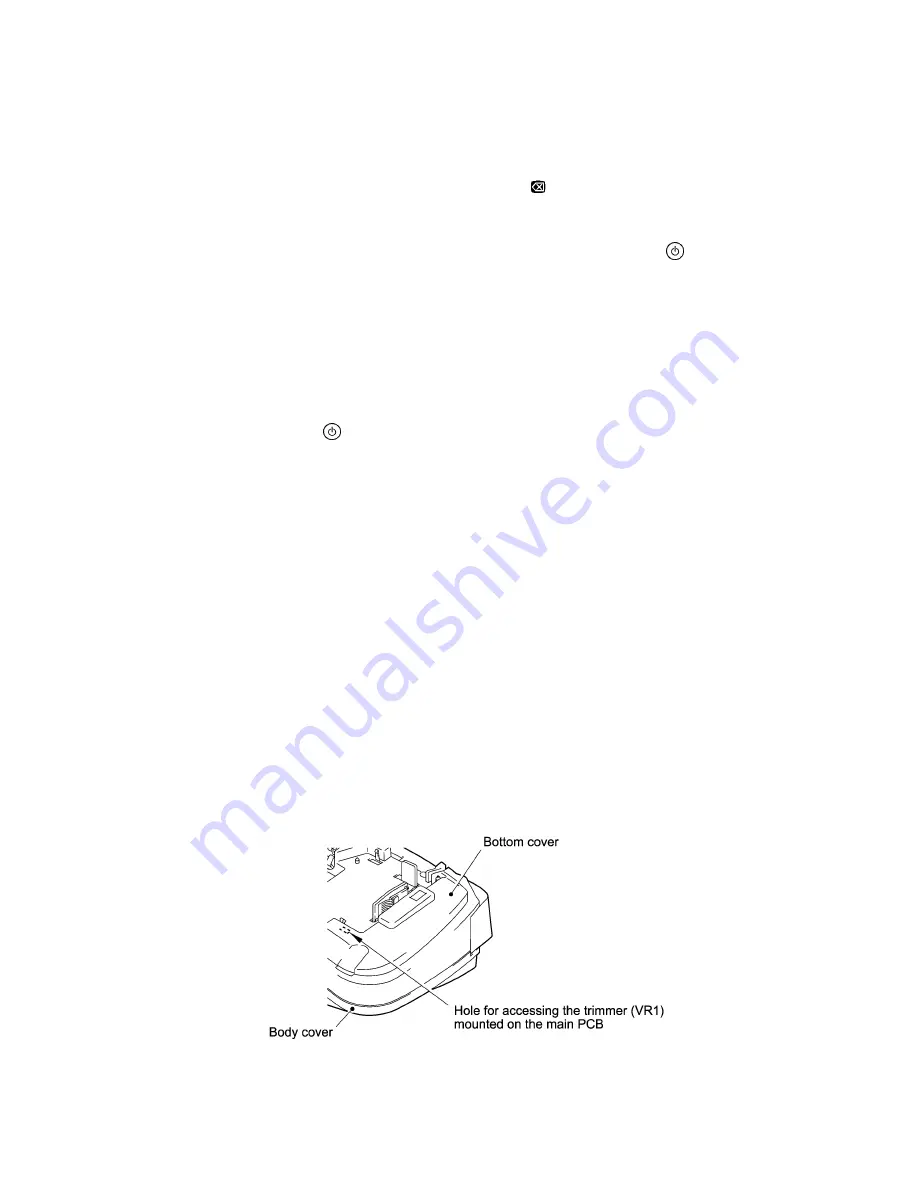
If the cut tape is out of the specified range, insert the tip of a screwdriver
through the hole provided in the bottom cover and rotate the trimmer (VR1) on
the main PCB to adjust the tape feeding length.
Rotating the VR1 clockwise will shorten the tape feeding length; rotating it
counterclockwise will lengthen it.
If any problem is found, go to the troubleshooting in Chapter IV.
Figure 2.2-22 Adjusting the Trimmer (VR1) on the Main PCB
Summary of Contents for P-touch 65
Page 1: ...SERVICE MANUAL MODEL P touch 65 P touch HOME HOBBY P touch One ...
Page 2: ...SERVICE MANUAL MODEL P touch 65 P touch HOME HOBBY P touch One ...
Page 5: ...Chapter I SPECIFICATIONS ...
Page 9: ...I 3 Figure 1 1 2 Key Arrangement ...
Page 11: ...Chapter II MECHANISMS ...
Page 35: ...Chapter III ELECTRONICS ...
Page 41: ...III 5 Figure 3 2 4 Key Scan Timing Scheme and Scanning Pulse Outputs ...
Page 47: ...III 11 Figure 3 2 11 Timing Chart for Thermal Head Drive ...
Page 52: ...Chapter IV TROUBLESHOOTING ...
Page 55: ...IV 2 4 1 3 Troubleshooting Flows 1 Tape feeding failure ...
Page 56: ...IV 3 ...
Page 57: ...IV 4 ...
Page 58: ...IV 5 2 Printing failure ...
Page 59: ...IV 6 ...
Page 60: ...IV 7 ...
Page 61: ...IV 8 3 Powering failure Nothing appears on the LCD ...
Page 62: ...IV 9 ...
Page 63: ...IV 10 4 No key entry possible ...
Page 64: ...IV 11 5 Abnormal LCD indication ...
Page 65: ...APPENDICES Circuit Diagrams A Main PCB B Sub PCB for P touch 65 and P touch One only ...


