


USER’S GUIDE
iv
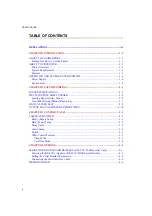
TABLE OF CONTENTS
CHAPTER 1 INTRODUCTION.....................................................................................1–1
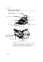
Printer Overview ............................................................................................................1–2
System Requirements .....................................................................................................1–3
Features ..........................................................................................................................1–3
OPERATING AND STORAGE ENVIRONMENT ...........................................................1–6
CHAPTER 2 PAPER HANDLING.................................................................................2–1
PAPER SPECIFICATIONS................................................................................................2–1
MULTI-PURPOSE SHEET FEEDER................................................................................2–4
Loading Paper into the Feeder........................................................................................2–5
Two Side Printing (Manual Duplexing) .........................................................................2–7
MANUAL FEED SLOT.....................................................................................................2–8
OUTPUT TRAY AND PAPER SUPPORT WIRE ...........................................................2–10
CHAPTER 3 CONTROL PANEL ..................................................................................3–1
Ready (Paper) Lamp.......................................................................................................3–1
Data (Toner) Lamp .........................................................................................................3–2
Drum Lamp ....................................................................................................................3–2
Alarm Lamp ...................................................................................................................3–2
Switch.............................................................................................................................3–3
Other Control Features ...................................................................................................3–3
Sleep Mode.................................................................................................................3–3
Test Print Mode ..........................................................................................................3–4
CHAPTER 4 OPTIONS...................................................................................................4–1
SERIAL INTERFACE BOARD RS100M (For HL-730 / 730Plus series Only) ..................4–1
Selecting the RS-422A (Apple) or RS-232C (IBM) Serial Interface .............................4–1
Setting the Serial Interface Parameters...........................................................................4–2
Connecting the Serial Interface Cable ............................................................................4–4
Summary of Contents for HL-720
Page 1: ...SERVICE MANUAL MODEL HL 720 730 730Plus R LASER PRINTER ...
Page 36: ...II 19 1 3 10 Engine I O HL 720 Fig 2 21 shows the engine interface circuit Fig 2 21 ...
Page 37: ...II 20 HL 730 730Plus Fig 2 22 shows the engine interface circuit Fig 2 22 ...
Page 61: ... Fig 3 18 2 4 1 1 1 ...
Page 92: ...SERVICE MANUAL MODEL HL 760 R LASER PRINTER ...
Page 109: ...II 8 1 3 4 DRAM Two 4M bit DRAMs x 16bits are used as the RAM Fig 2 6 ...
Page 113: ...II 12 1 3 10 Engine I O Fig 2 12 shows the engine interface circuit Fig 2 12 ...
Page 114: ...II 13 1 3 11 Paper Feed Motor Drive Circuit Fig 2 13 ...
Page 133: ...Appendix 2 Main PCB Circuit Diagram 1 3 CODE UK3227000 B48K272CIR 1 3 NAME ...
Page 134: ...Appendix 3 Main PCB Circuit Diagram 2 3 CODE UK3227000 B48K272CIR 2 3 NAME ...
Page 135: ...CODE UK3227000 B48K272CIR 3 3 NAME Appendix 4 Main PCB Circuit Diagram 3 3 ...


