V
- 2
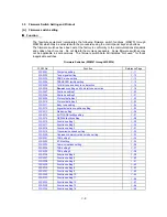
2. LIST OF MAINTENANCE-MODE FUNCTIONS
Maintenance-mode Functions
Function
Code
Function
Reference
Subsection
(Page)
01
EEPROM Parameter Initialization
3.1 (V-4)
02
03
04
05
Printout of Scanning Compensation Data
3.2 (V-5)
06
07
08
ADF* Performance Test
3.3 (V-7)
09
Test Pattern 1
3.4 (V-8)
10
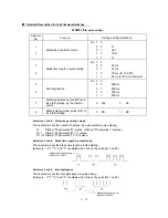
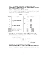
Firmware Switch Setting
3.5 (V-9)
11
Printout of Firmware Switch Data
3.5 (V-49)
12
Operational Check of LCD
3.6 (V-50)
13
Operational Check of Control Panel PCB
(Check of Keys and Buttons)
3.7 (V-50)
32
Sensor Operational Check
3.8 (V-52)
54
Fine Adjustment of Scanning Start/End Position
3.9 (V-53)
55
CIS Scanner Area Setting
3.10 (V-54)
74
EEPROM Customizing
3.11 (V-54)
82
Equipment Error Code Indication
3.12 (V-55)
87
Output of Transmission Log to the Telephone Line
3.13 (V-55)
91
EEPROM Parameter Initialization (except the telephone number
storage area)
3.1 (V-4)
99
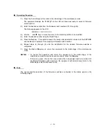
Exit from the Maintenance Mode
---- (V-1)
-----
Document Draw Adjustment
3.14 (V-56)
* ADF: Automatic document feeder
Summary of Contents for FAX 750
Page 4: ...CHAPTER I GENERAL DESCRIPTION ...
Page 11: ...CHAPTER II INSTALLATION ...
Page 12: ...CHAPTER III THEORY OF OPERATION ...
Page 14: ...III 1 1 OVERVIEW Not provided on the FAX 910 ...
Page 24: ...III 11 Active Gears on the Inner Side of the Drive Unit ...
Page 26: ...III 13 Active Gears on the Inner Side of the Drive Unit ...
Page 30: ...III 17 Location of Sensors and Actuators 1 ...
Page 31: ...III 18 Not provided on the FAX 910 Location of Sensors and Actuators 2 ...
Page 34: ...III 21 FAX750 FAX770 FAX 910 FAX 920 FAX 921 MFC 925 FAX870MC FAX 930 FAX 931 MFC970MC ...
Page 39: ...CHAPTER IV DISASSEMBLY REASSEMBLY LUBRICATION AND ADJUSTMENT ...
Page 44: ...IV 4 n n Disassembly Order Flow ...
Page 48: ...IV 8 4 Disconnect the panel main harness ...
Page 52: ...IV 12 ...
Page 70: ...IV 30 Remove the two screws and lift up the paper feed chute ...
Page 72: ...IV 32 ...
Page 78: ...IV 38 ...
Page 86: ...IV 46 1 17 Harness Routing ...
Page 88: ...IV 48 ...
Page 89: ...IV 49 2 LF roller ASSY 3 Platen frame ASSY ...
Page 90: ...IV 50 ...
Page 91: ...IV 51 4 Separation roller and main frame ...
Page 92: ...CHAPTER V MAINTENANCE MODE ...
Page 99: ...V 6 Scanning Compensation Data List ...
Page 150: ...CHAPTER VI ERROR INDICATION AND TROUBLESHOOTING ...
Page 168: ...July 98 5X4401 Printed in Japan ...
Page 177: ......
Page 178: ......
Page 182: ......
Page 184: ......
Page 197: ......
Page 198: ......
Page 202: ......
Page 216: ......
Page 218: ......


