V
- 32
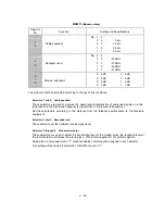
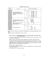
WSW19
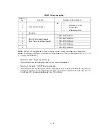
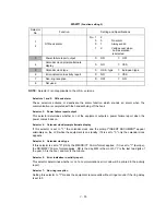
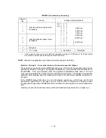
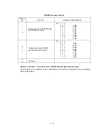
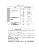
(Transmission speed setting)
Selector
No.
Function
Setting and Specifications
1
|
3
First transmission speed choice
for fallback
No. 1
2
3
No. 4
5
6
0
0
0
:
2,400 bps
0
0
1
:
4,800 bps
0
1
0
:
7,200 bps
4
|
6
Last transmission speed choice
for fallback
0
1
1
:
9,600 bps
1
0
0
:
12,000 bps *
1
0
1
:
1
1
0
:
14,400 bps *
1
1
1
:
7
Not used.
8
V. 17 mode
0:
Permitted
1:
Prohibited
•
In those models with a maximum of 9600 bps capability, selection of 12,000 bps or 14,400 bps will still
only produce a set speed automatically reduced to 9600 bps.
NOTE:
Selector 8 is applicable only to those models that support 14,400 bps.
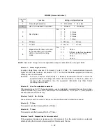
l
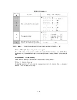
Selectors 1 through 6:
First and last choices of transmission speed for fallback
These selectors are used to set the MODEM speed range. With the first transmission speed choice
specified by selectors 1 through 3, the equipment attempts to synchronize the data transmission via
the MODEM. If the synchronization fails, the equipment automatically steps down to the next
lowest speed and attempts to synchronize the data transmission again. The equipment repeats this
sequence while stepping down the transmission speed to the last choice specified by selectors 4
through 6.
If the MODEM always falls back to a low transmission speed (e.g., 4,800 bps), set the first
transmission speed choice to the lower one (e.g., modify it from 12,000 bps to 7,200 bps) in order
to deactivate the high-speed MODEM function and reduce the training time for shorter transmission
time.
Generally, to save the transmission time, set the last transmission speed choice to a higher one.
Summary of Contents for FAX 750
Page 4: ...CHAPTER I GENERAL DESCRIPTION ...
Page 11: ...CHAPTER II INSTALLATION ...
Page 12: ...CHAPTER III THEORY OF OPERATION ...
Page 14: ...III 1 1 OVERVIEW Not provided on the FAX 910 ...
Page 24: ...III 11 Active Gears on the Inner Side of the Drive Unit ...
Page 26: ...III 13 Active Gears on the Inner Side of the Drive Unit ...
Page 30: ...III 17 Location of Sensors and Actuators 1 ...
Page 31: ...III 18 Not provided on the FAX 910 Location of Sensors and Actuators 2 ...
Page 34: ...III 21 FAX750 FAX770 FAX 910 FAX 920 FAX 921 MFC 925 FAX870MC FAX 930 FAX 931 MFC970MC ...
Page 39: ...CHAPTER IV DISASSEMBLY REASSEMBLY LUBRICATION AND ADJUSTMENT ...
Page 44: ...IV 4 n n Disassembly Order Flow ...
Page 48: ...IV 8 4 Disconnect the panel main harness ...
Page 52: ...IV 12 ...
Page 70: ...IV 30 Remove the two screws and lift up the paper feed chute ...
Page 72: ...IV 32 ...
Page 78: ...IV 38 ...
Page 86: ...IV 46 1 17 Harness Routing ...
Page 88: ...IV 48 ...
Page 89: ...IV 49 2 LF roller ASSY 3 Platen frame ASSY ...
Page 90: ...IV 50 ...
Page 91: ...IV 51 4 Separation roller and main frame ...
Page 92: ...CHAPTER V MAINTENANCE MODE ...
Page 99: ...V 6 Scanning Compensation Data List ...
Page 150: ...CHAPTER VI ERROR INDICATION AND TROUBLESHOOTING ...
Page 168: ...July 98 5X4401 Printed in Japan ...
Page 177: ......
Page 178: ......
Page 182: ......
Page 184: ......
Page 197: ......
Page 198: ......
Page 202: ......
Page 216: ......
Page 218: ......

