


RH-9820 UPPER THREAD NIPPER DEVICE SET
3
2-1.
バルブユニットの取り付け方
2-1. Installing the valve unit
2-1.
阀门组的安装法
2-1. Instalación del unidad de válvula
1.
バルブユニット
(1)
の
No.34
と
No.35
の穴に、
レジューサ
(2)[2
本
]
を差し込みます。
2.
バルブユニット
(1)
をエアーユニット
(3)
の横に、木ねじ
(4) [2
本
]
で取り付けます。
*
他の部品のじゃまにならない位置に取り付けてください。
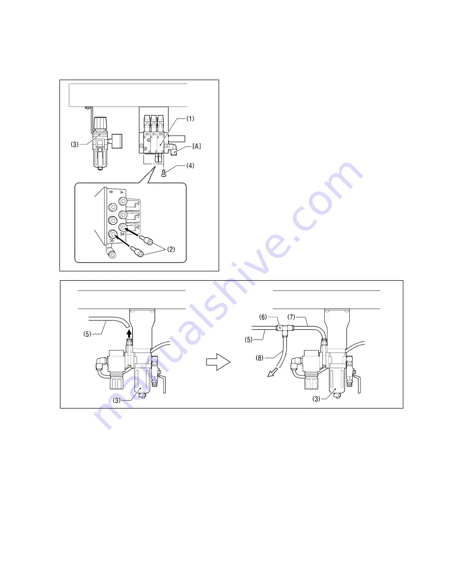
1. Insert the two reducers (2) into holes No.34 and No.35 in
the valve unit (1).
2. Install the valve unit (1) to the side of the air unit (3) with the
two screws (4).
* Install the valve unit in a position where it will not obstruct
any other parts.
1.
在阀门组
(1)
的
No.34
和
No.35
的孔处,插入变径销
(2)[2
个
]
。
2.
在空压装置
(3)
的旁边用木螺钉
(4)[2
个
]
将阀门组
(1)
固定。
*
请安装在不妨碍别的零部件的位置。
1. Inserte las dos tapas (2) en los agujeros No.34 y No.35 en
la unidad de válvula (1).
2. Instale la unidad de válvula (1) a un costado de la unidad
neumática (3) con los dos tornillos (4).
* Instale la unidad de válvula en una posición donde no
obstruya ninguna otra parte.
バルブユニット
(1)
の
[A]
へ
To [A] of valve unit (1)
连接到阀门组
(1)
的
[A]
上
[A] de la unidad de válvula (1)
3.
エアーユニット
(3)
からエアーチューブ
(5)
を取り外します。
4.
継ぎ手
(6)
を使用し、エアーチューブ
(5)
、
(7)
、
(8)
を図のように接続します。
3. Disconnect the air tube (5) from the air unit (3).
4. Use the joint (6) to connect the air tubes (5), (7) and (8) as shown in the illustration.
3.
将空压装置
(3)
从空气接管
(5)
处取下。
4.
使用管接头
(6)
,如图所示,连接空气接管
(5)
,
(7)
,
(8)
。
3. Desconecte el tubo de aire (5) de la unidad neumática (3).
4. Use la unión (6) para conectar los tubos de aire (5), (7) y (8) tal como se indica en la figura.
0572B
0945B