Bronkhorst®
Instruction Manual ES-FLOW™
9.17.145E
42
Communication through standard connector (RS-232/RS-485)
Use the following parameters to configure the instrument for communication through the 8-pin M12 connector:
Fieldbus 2 Address
Type
Access
Range
FlowDDE
FLOW-BUS
Modbus
Unsigned char
RW
0…255
309
124/10
0x0F8A/3979
Fieldbus 2 Baud Rate
Type
Access
Range
FlowDDE
FLOW-BUS
Modbus
Unsigned long
RW
0…1.0E10
310
124/9
0xFC48…0xFC49/64585…64586
Fieldbus 2 Parity
Type
Access
Range
FlowDDE
FLOW-BUS
Modbus
Unsigned char
RW
0…2
336
124/12
0x0F8C/3981
The following values are supported:
Value
Description
0
No parity
1
Odd parity
2
Even parity
3.4.6
Controller
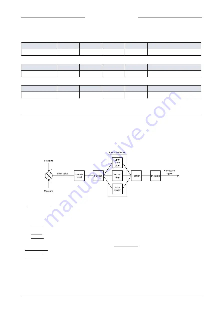
The picture below shows a basic diagram of the PID controller algorithm (proportional, integral, derivative) used by digital
Bronkhorst® instruments.
The controller speed controls the overall performance of the controller algorithm. Basically, to adjust the controller
response, only the controller speed needs to be changed.
The algorithm is based upon the difference between the setpoint and the measured value (called the error value). The
correction signal to eliminate the error is assembled from 3 basic components:
·
The P-action (proportional) multiplies the error value by a constant factor, to adjust the measure towards the (new)
setpoint.
·
The I-action (integral) amplifies the correction signal with a factor depending on the integral of the error value over time.
·
The D-action (derivative) reduces the strength of the P-action, to prevent overshoot when the (new) setpoint is reached.
The proportional action is enhanced by one of three additional response factors, depending on the control cycle stage:
·
Open from zero: the setpoint is larger than zero and the measured value is below 2% of the full scale range.
·
Normal step: the measured value differs more than 2% from the setpoint, typically after changing the setpoint (step).
·
Stable situation: the measured value differs less than 2% from the setpoint.


