background image

30

Section D – Electrical Components

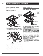
Motor Centrifugal Switch 

Assembly

REMOvE AND REPLACE

This  switch  reverses  the  motor  when  peak  load  is 
reached.

SWITCH

POWER UNIT 

MECHANISM

SCREWS

Remove the control panel assembly from the front of 

1. 

the  unit  (see  Control  Panel  Assembly,  Remove  and 
Re-install).

SCREWS

Remove  two  Phillips  head  screws  and  the  switch 

2. 

from the bottom of the motor.

Noting  their  locations,  transfer  the  wires  to  the 

3. 

replacement switch.

Install the switch and secure with two Phillips head 

4. 

screws.

Motor Capacitor

TEST, REMOvE AND REPLACE

CAPACITOR

SHIELD

POWER 

UNIT

MAIN 

MOTOR

SCREWS

The capacitor provides power required to start the main 
motor and improves overall efficiency.

Use an electrically-insulated tool to short the capacitor 
terminals together. This will ensure the capacitor has 
fully  discharged  and  will  prevent  shock  if  any  body 
part comes in contact with the terminals.

Before testing with a multi-meter, there are two indicators 
you can look for on the outside of the capacitor to see 
if  it  is  bad.  If  you  spot  corrosion  around  the  terminals 
or  bulging  electrolyte  (ceramic  outer  material),  then  the 
capacitor is leaky and must be replaced.

To access and test the capacitor:

Remove the control panel assembly from the front of 

1. 

the compactor (see Control Panel Assembly, Remove 
and Re-install).

Summary of Contents for Elite 15XESSEXF

Page 1: ...99044663A November 2010 Service Manual Trash Compactor Models 15XESSEXF Broan NuTone LLC 926 West State Street Hartford WI 53027 1 800 637 1453 ...

Page 2: ...ions are correct and secure All electrical leads are properly dressed and secured away from sharp edges high temperature components and moving parts All non insulated electrical terminals connectors heaters etc are adequately spaced away from all metal parts and panels All safety grounds both internal and external are correctly and securely connected All panels are properly and securely re assembl...

Page 3: ... install 17 Drive Wheels 17 Remove and Replace 17 Ram Screw Assembly 18 Remove and Replace 18 Section D Electrical Components 21 Start Switch 22 Remove and Replace 22 Access to Components 22 Remove Cabinet Cover 22 Re install Cabinet Cover 24 Control Panel Assembly 25 Remove and Re install 25 Display Module Assembly 26 Remove and Re install 26 Power Supply Board 26 Remove and Re install 26 Control...

Page 4: ...es food wastes etc When you start the compactor an electrically powered ram moves down into the trash bucket compresses the trash and then returns to the UP position and shuts off automatically NOTE The ram travels about 2 3 of the way down into the trash bucket Because of this the trash bucket must be at least 1 3 full before you will notice any compression Electrical components SECTION D Power U...

Page 5: ...tion Built in Installation mounting straps top of compactor front of compactor Two under counter mounting straps are provided Use these straps to secure the compactor to the underside of a countertop Fasten the slotted end of the straps to the compactor using the holes in the top of the compactor cabinet as shown NOTE When installation compactor under granite or solid surface countertops bend the ...

Page 6: ...oors and also trim the unit up to fit an under counter installation back of compactor wood block adjusting screws slots rollers To level the back of the compactor Tip the back of compactor up and onto a wood block Loosen the adjusting screws only far enough to move the rollers to a higher or lower slot Retighten the adjusting screws and remove the wood block front of compactor wood block leveling ...

Page 7: ...s a number of sub assemblies These include the trash bucket the door the motor the ram and the electrical controls and components Legend A Trash Bucket B Bucket Handle C D Slide Rails E Door Assembly F Safety Interlock Actuator G Gasket Assembly H Top Trim Cover a b C D F G e H ...

Page 8: ...and right bucket slide release tabs 3 while pulling the bucket out of the cabinet Bucket Handle Remove and Replace The plastic bucket handle may receive a lot of wear and tear simply because the operator uses it every time he or she places trash into the compactor or removes or replaces the bag If the handle is scratched chipped or broken replace it Bucket Handle Screw Remove two Phillips head scr...

Page 9: ...cessary to slide the inner rail to access both screws Remove the slide rail from the cabinet 3 To re install place slide rail onto the three spring 4 clips inside of the cabinet Align holes in rail with bracketed holes on inside of cabinet and secure with two Phillips head screws Repeat for other side Slide Rails Bucket Remove and Re install Rail Bucket Screw Screws Remove four Phillips head screw...

Page 10: ...of the door away from the cabinet To re install lift the door insert the upper hinge pin 3 into the upper door bushing and move the door into place Insert the lower hinge pin from Step 1 and tighten securely REVERSE DOOR Hinge POSITION The compactor comes from the factory with the door in the right hand opening position Use the following instructions to reverse the door Remove the door see Remove ...

Page 11: ...all the door see Remove and Re install 6 Safety Interlock Actuator Remove and Re install This safety device prevents the compactor from operating except when the door is closed NOTE If the interlock actuator should break off the compactor will not function replace it promptly DOOR INSULATION PAD INNER DOOR PANEL 14 SCREWS ACTUATOR SCREW Remove the 14 Phillips head screws from the inner 1 door pane...

Page 12: ... Components Control Panel Assembly Lift the outer edge of the gasket to expose the 3 retainer strips and the screws that are used to fasten the strips to the cabinet NOTE There are six retainer strips two each on the top and bottom and one each for the left and right sides Remove the Phillips head screws that secure the 4 retainer strips to the cabinet then remove the strips from underneath the ga...

Page 13: ...l Remove the door see Door Assembly Remove and 1 Re install SCREWS Remove the four Phillips head screws that secure the 2 top trim cover to the cabinet Pull the top trim cover away from the cabinet 3 Re install in reverse order Be careful not to over 4 tighten screws ...

Page 14: ...14 Section C Power Unit Mechanism b D C A Legend A Drive Belt B Main Motor C Complete Power Unit Mechanism D Ram Screw Assembly ...

Page 15: ...x head 3 cap screws Rotate motor to loosen belt for removal IMPORTANT Before installing a new drive belt follow the instructions below to align the height of both ram screws Top Frame RAM Measure the distance from the underside of the top 4 frame to the bottom edge of the ram at the front and rear of the power unit If the measurements are different rotate the ram screw 5 drive wheels as necessary ...

Page 16: ...stall Mark the location of all wire connections and ties on 3 the motor then disconnect the wires IDLER WHEEL 3 HEAD CAP SCREWS LOCK WASHERS AND FLAT WASHERS NOTE For illustration purposes the view is shown with the drive wheels removed Use an open end socket or crescent wrench to 4 remove the idler wheel Support the motor from underneath and remove 5 the three head cap screws lock washers and fla...

Page 17: ...he power unit and remove the two Phillips 3 head screws from each of four support rods Remove the power unit mechanism 4 Installation is the reverse of removal 5 Drive Wheels Remove and Replace SPRING WASHER BEARING THRUST WASHER DRIVE WHEEL IDLER WHEEL 3 SCREWS MOTOR Remove cabinet cover see 1 Electrical Components Access to Components Remove the belt cover and drive belt see above 2 and follow t...

Page 18: ...lt see Drive Belt Remove and 2 Re install Remove drive wheels see Drive Wheels Remove 3 and Replace Release Tab RAM Compaction Plate Remove the compaction plate by releasing the tab 4 on the front of the ram and pulling the plate down and away from the ram Note When re installing the plate insert the rear tab into the slot at the rear of the ram then press up on the front of the plate until it lat...

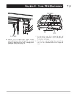
Page 19: ...bly Note orientation of bracket during removal as they activate the limit switches Pin Fasteners Pin Slot Turn the ram until the top pin indexes 90 from the 7 pin slot remove two hex screws lock washers and flat washers fasteners Turn the ram as required to align the ram pin with the 8 slot in the top frame and lower the ram through the hole ...

Page 20: ...n thrust washer bearing and upper 9 bearing housing from the ram Lower the ram screw assembly through the center 10 stabilizer plate BOSSES Notches IMPORTANT On re assembly index the bosses on the top bearing housing with the corresponding notches in the bearing Brackets must be positioned correctly as they activate the limit switches See illustration at left Re assembly is the reverse of disassem...

Page 21: ...trol Panel Assembly C Display Module Assembly D Power Supply Board E Control Board F Cabinet Safety Interlock Switch G Key Switch Assembly H Upper Limit Switch Assembly I Lower Limit Switch J Motor Centrifugal Switch Assembly K Motor Capacitor L Odor Disk Gear Motor Assembly M Start Switch ...

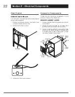
Page 22: ... order to access the electrical components it is first necessary to remove the cabinet cover Remove Cabinet Cover Remove the bucket from the compactor see 1 Cabinet Trash Bucket Remove the door assembly the 2 bottom door 2 gasket retainers see Cabinet Door Assembly Remove the back panel by first removing the Phillips 3 head screw that secures the power cord cable clamp to the back panel and then r...

Page 23: ... notches on the right and left sides must appear on the lower part of the bag storage Screws Remove six Phillips head screws each that secure the 6 front and rear of the stabilizer plates to the cabinet cover rear view shown Grommet To remove the power cord at the back of the unit 7 rotate the power cord grommet 90º to the right then slide the cord out of the slot Temporarily place the cord in the...

Page 24: ...r edges of the cover and lift it off the unit tilting it forward and back as required Re install Cabinet Cover Pins 1 To re install the cabinet cover lift the cover over the top of the unit and allow it to rest temporarily on the top of the locator pins Insert the right and left stabilizer plates but do not 2 secure them in place they will rest temporarily on top of the ram Gently move the cover s...

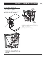
Page 25: ...g storage and the odor control disk tray Screws Control Panel Screws On the front of the unit remove the five Phillips head 1 screws that secure the control panel assembly to the cabinet cover Wiring Harnesses Wiring Harness After removing these five screws open odor disk tray 2 pull the panel away from the cabinet and disconnect the five wiring harnesses Installation is the reverse of removal 3 ...

Page 26: ...ry connector and odor disk 2 switch from the control panel Screws Remove five Phillips head screws and the display 3 module assembly from the control panel Installation assembly is the reverse of removal NOTE 4 First install display module assembly to panel then re attach wiring Power Supply Board Remove and Re install The power supply board directs electrical power to all areas of the compactor i...

Page 27: ...move and Re install The control board is used to electronically connect the compactor s electronic components Control Board Control Panel Screws Display Panel Remove the control panel assembly see Control 1 Panel Assembly Remove and Re install Remove rear cover from the display module assembly see Display Module Assembly Remove and Re install Screws Wire Connector Remove the wire harnesses from co...

Page 28: ... Remove three Phillips head screws and lift the switch 2 assembly away from the housing Noting their locations transfer the wires to the 3 replacement switch Installation is the reverse of removal 4 Interlock Switch Assembly Remove and Re install The interlock switch assembly is a safety feature The switch prevents the compactor from operating unless the door is safely closed Remove the control pa...

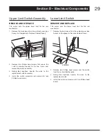
Page 29: ...y Noting their locations transfer the wires to the 3 replacement switch assembly Install the switch assembly and secure with four 4 Phillips head screws Lower Limit Switch Remove and Replace This switch sets the lower travel limit for the ram mechanism Remove the back panel from the cabinet cover see 1 Access to Components Remove Cabinet Cover Screws Remove two Phillips head screws and the switch ...

Page 30: ...apacitor Shield Power Unit Main Motor Screws The capacitor provides power required to start the main motor and improves overall efficiency Useanelectrically insulatedtooltoshortthecapacitor terminals together This will ensure the capacitor has fully discharged and will prevent shock if any body part comes in contact with the terminals Before testing with a multi meter there are two indicators you ...

Page 31: ...cale if available to check resistance across the wire terminals The needle should jump toward zero ohms and quickly move back to infinity Note Some less sophisticated meters will only tell you if the capacitor is good or bad If the needle does not move if the needle reads a 6 constant value or near zero ohms or if the needle jumps toward zero and then moves back to constant high resistance not inf...

Page 32: ...this item place ram in lowest position 1 by setting compact mode to hold Press start button and close door Ram will run down and stop Disconnect power Open bucket door 2 Remove the control panel assembly from the front of 3 the compactor see Control Panel Assembly Remove and Re install Screws RemovetwoPhillipsheadscrews inaboveillustration 4 shown in place from the top from the bottom of the right...

Page 33: ...ic thermal cutout may have engaged Wait a few minutes to allow unit 6 to cool down cutout will reset itself Motor defective 7 Replace motor or complete 7 power mechanism Defective control module 8 Replace control board or 8 complete display module assembly Unable to open or close trash bucket Slide rail s damaged 1 Replace rail s 1 Trash bucket damaged or bent 2 Replace trash bucket assembly 2 Deb...

Page 34: ... assembly Defective control board 2 Replace control board or 2 complete display module assembly Defective power board 3 Replace power board or 3 complete display module assembly During compaction cycle the motor runs but the ram doesn t move Drive belt is damaged Replace drive belt Compactor does not compact cans or bottles Compaction force appears weak Insufficient amount of trash in 1 trash buck...

Page 35: ...fective centrifugal switch 2 Replace centrifugal switch 2 assembly Motor hums after ram returns to the up position Defective upper limit switch assembly Replace upper limit switch assembly Ram continues to run with the door open Defective interlock switch Replace interlock switch assembly During NORMAL compact mode ram runs down and doesn t return up Motor hums after reaching the bottom position D...

Page 36: ...ications Table Broan 15 Inch Wide Automatic Trash Compactor Models 15XESSEXF 15XESSEXG Volts Hz Amps Capacity Compactor Weight Dimensions 220 240 50 60 3 0 1 55 ft 3 30 lbs 3000 lbs 6 to 1 165 lbs packaged 34 1 8 H min 14 7 8 W 21 1 2 D ...

Page 37: ...H MOTOR MAIN START RELAY BROWN RED ORANGE WHITE WHITE BLUE GREEN YELLOW ORANGE RED BROWN BLACK BLACK WHITE COMPACT MODE RELAY WHITE RED RED BLUE RED BLUE 240V BROWN 0V START DOWN SCHEMATIC SHOWS UNIT WITH RAM IN UP POSITION KEY SWITCH OFF DOOR OPEN AND COMPACT MODE NORMAL DOOR SENSOR SWITCH RAM UP SENSOR SWITCH START BUTTON ODOR DISK SWITCH SENSOR USER INTERFACE DC 9V BATTERY BACK UP SWITCH RAM LO...

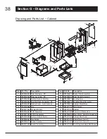
Page 38: ...Assembly 9 S99527484 AC DC Assembly 10 S99526866 Safety Interlock Switch 11 S99526867 Key Switch 12 S99526871 Bucket Handle 13 S99527485 Bucket Assembly Item Part No Description 14 S99526872 Bucket Slide Assembly 15 S99526854 Door Gasket Assembly 16 S99526873 Leveling Leg 17 S99526874 Leveling Wheel Assembly 18 S99526875 Cabinet Stand Base 19 S99527074 Start Switch 20 S99527487 Cabinet 21 S9952748...

Page 39: ...t 28 S99526889 Drive Wheel 29 S99526890 Idler Wheel 30 S99526891 Upper Limit Switch Assembly 31 S99527019 Lower Limit Switch 32 S99527493 Main Motor Item Part No Description 33 S99527494 Motor Capacitor 34 S99526893 Centrifugal Switch Assembly 35 S99526895 Ram Screw Assembly 36 S99527020 Latch Assembly Compaction Plate 37 S99526882 Compaction Plate SS ...

Reviews: