background image

20

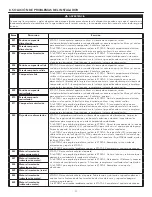
8. SOLUCIÓN DE PROBLEMAS DEL INSTALADOR 


ADVERTENCIA

Se aconseja llevar guantes y gafas de protección porque algunos procedimientos de diagnóstico pueden exigir que el aparato esté 
funcionando durante el procedimiento. Tenga cuidado con las piezas móviles y los componentes eléctricos para evitar todo riesgo de 
lesiones.

!

E

rror

D

Escripción

s

olución

E01

Posición compuerta
alimentación

ETAPA 1: Desenchufar el aparato, verificar el sistema de compuertas, retirar 
cualquier obstáculo indeseable o suciedad (puede ser necesario quitar los filtros y el núcleo 
para acceder al sistema de compuertas). Enchufar el aparato. 
Si la ETAPA 1 no arregló el problema, realizar la ETAPA 2: Abrir el compartimento eléctrico, 
verificar si el conector J5 (blanco) está bien insertado, verificar si hay cables sueltos. 
Si la ETAPA 2 no arregló el problema, realizar la ETAPA 3: Si la compuerta no se mueve, 
desenchufar J7 (rojo) de la tarjeta electrónica, conectar el conector blanco del sistema de 
compuertas en J7. Si la compuerta mueve (el sistema sigue indicando un error), reemplazar 
el conjunto electrónico. Si no funciona, reemplazar el sistema de compuertas.

E02

Parada compuerta
alimentación

E03

Compuerta alimentación

E05

Posición compuerta salida

ETAPA 1: Desenchufar el aparato, verificar el sistema de compuertas, retirar 
cualquier obstáculo indeseable o suciedad (puede ser necesario quitar los filtros y el núcleo 
para acceder al sistema de compuertas). Enchufar el aparato. 
Si la ETAPA 1 no arregló el problema, realizar la ETAPA 2: Abrir el compartimento eléctrico, 
verificar si el conector J7 (rojo) está bien insertado, verificar si hay cables sueltos. 
Si la ETAPA 2 no arregló el problema, realizar la ETAPA 3: Si la compuerta no se mueve, 
desenchufar J5 (blanco) de la tarjeta electrónica, conectar el conector blanco del sistema de 
compuertas en J5. Si la compuerta mueve (el sistema sigue indicando un error), reemplazar 
el conjunto electrónico. Si no funciona, reemplazar el sistema de compuertas.

E06

Parada compuerta salida

E07

Compuerta salida

E09

Posición compuerta
recirculación

ETAPA 1: Desenchufar el aparato, verificar el sistema de compuertas, retirar 
cualquier obstáculo indeseable o suciedad (puede ser necesario quitar los filtros y el núcleo 
para acceder al sistema de compuertas). Enchufar el aparato. 
Si la ETAPA 1 no arregló el problema, realizar la ETAPA 2: Abrir el compartimento eléctrico, 
verificar si el conector J6 (azul) está bien insertado, verificar si hay cables sueltos. 
Si la ETAPA 2 no arregló el problema, realizar la ETAPA 3: Si la compuerta no se mueve, 
desenchufar J5 (blanco) de la tarjeta electrónica, conectar el conector azul del sistema de 
compuertas en J5. Si la compuerta mueve (el sistema sigue indicando un error), reemplazar 
el conjunto electrónico. Si no funciona, reemplazar el sistema de compuertas.

E10

Parada compuerta
recirculación

E11

Compuerta recirculación

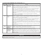
E22

Flujo de aire alimentación

ETAPA 1: Comprobar visualmente el sistema de compuertas de alimentación. Limpiar los 
filtros, los registros de distribución y las bocas de admisión exterioras. Inspeccionar los 
conductos para asegurarse que no están comprimidos o doblados. 
Si la ETAPA 1 no arregló el problema, realizar la ETAPA 2: Retirar los conductos de la línea de 
alimentatión. En la pantalla LCD, seleccionar MAX para verificar si el aparato puede lograr el 
flujo seleccionado. En caso de que así sea, verificar la línea de los conductos. 
Si la ETAPA 2 no arregló el problema, realizar la ETAPA 3: En la pantalla LCD, seleccionar los 
valores de ajuste de los flujos MIN y MAX y después reinicializar el aparato. El valor de flujo 
MAX aparecerá en la pantalla LCD. Si el flujo MAX es superior al flujo MAX deseado, ajustar 
los flujos MAX y MIN. 
Si la ETAPA 3 no arregló el problema, realizar la ETAPA 4: Reemplazar el ventilador de 
alimentación y repetir la ETAPA 3.
Si la ETAPA 4 no arregló el problema, realizar la ETAPA 5: Reemplazar el conjunto electrónico.

E23

Motor alimentación
(sobrecarga motor)

ETAPA 1: Desenchufar/enchufar el aparato.
Si la ETAPA 1 no arregló el problema, realizar la ETAPA 2: Quitar el núcleo y retirar cualquier 
obstáculo o suciedad de la rueda de ventilación. 
Si la ETAPA 2 no arregló el problema, realizar la ETAPA 3: Desconectar J2 (blanco) y conectar 
un sistema de ventilador de repuesto. Si funciona, reemplazar el ventilador de alimentación. 
Si la ETAPA 3 no arregló el problema, realizar la ETAPA 4: Reemplazar el conjunto 
electrónico.

E27

Motor alimentación
(sobretensión motor)

E28

Motor alimentación
(duración motor)

E29

Motor alimentación (inicio)

E24

Motor alimentación
(sobretensión motor)

ETAPA 1: Desenchufar/enchufar el aparato. Sobretensión y subtensión se pueden observar 
con una fuerte fluctuación de la alimentación eléctrica de la casa y se pueden apagar el 
motor para protegerlo. 
Si la ETAPA 1 no arregló el problema, realizar la ETAPA 2: Reemplazar el conjunto electrónico.

E25

Motor alimentación
(subtensión motor)

Summary of Contents for B110H65RS

Page 1: ...NLINE AT www broan nutone com en us home customer service product registration For additional information visit www Broan NuTone com VB0341 FAULT INDICATOR DISPLAY REQUIREMENTS Recirculation mode is not offered on these models These products earned the ENERGY STAR by meeting strict energy efficiency guidelines set by Natural Resources Canada and the US EPA They meet ENERGY STAR requirements only w...

Page 2: ...avoid prematurely clogged filters turn the unit OFF during construction or renovation 2 Please read specification label on product for further information and requirements 3 Be sure to duct air outside Do not intake exhaust air into spaces within walls or ceiling or into attics crawl spaces or garage Do not attempt to recover the exhaust air from a dryer or a range hood 4 Intended for residential ...

Page 3: ...ll Control 11 3 2 ELECTRICAL CONNECTION TO OPTIONAL AUXILIARY WALL CONTROL 12 3 2 1 Electrical Connection to 20 40 60 Optional Auxiliary Wall Control 12 3 2 2 Electrical Connection to Dry Contact Optional Auxiliary Wall Control e g Crank Timer 12 3 3 CONNECTION TO THE CENTRAL FORCED AIR SYSTEM 13 3 3 1 Unit Operation Using a Dry Contact Connection 13 3 3 2 Unit Interconnection with Central Forced ...

Page 4: ...e insulated flexible ducts to and from the unit HRV units only close to a drain If no drain is close by use a pail to collect run off Away from hot chimneys electrical panel and other fire hazards Within 6 feet of a power source standard outlet Consumer Information A To ensure quiet operation of the H ERV each product model must be installed using sound attenuation techniques appropriate for the i...

Page 5: ...e the unit to the wall making sure that the 4 screws engage into a stud Always make sure that the unit is no more than 1 4 off level VD0486 VD0485 Suspended to the joists or trusts Slightly bend the brackets on the unit to insert the provided chains Hang the unit to the joists or trusts using the chains Springs are not required Always make sure that the unit is no more than 1 4 off level OR VD0487...

Page 6: ...n duct at least 10 feet away from the central forced air system A B This 10 ft distance applies only in areas where the outside temperature falls below the freezing point 32 F NOTE The central forced air system blower operation can be synchronized with the unit see section 3 3 It is recommended but not essential that the central forced air system blower runs when the unit is in operation 2 2 2 Exh...

Page 7: ...w recirculation mode to operate Unit should be synchronized with central forced air system operation to avoid condensation and mold growth in central forced air system distribution ducting if cooling mode of central forced air system is used Fresh air to building Stale air from building Stale air to outdoors Fresh air from outdoors This configuration is not recommended with high velocity central f...

Page 8: ...low Run the tube to the floor drain or to an alternate drain pipe or pail IMPORTANT If using a pail to collect water place the tube end approximately 1 inside the pail in order to prevent water from being drawn back up into the unit VO0290A 13 330 mm 13 330 mm VO0083 1 TIE WRAP 2 2 4 Installing Dual Exterior Hood Using Tandem Transition Kit Optional For units set at 110 CFM or less a Tandem transi...

Page 9: ... use screws to connect the ducts or transitions to the ports so as not to interfere with ports inner dampers operation A non functioning damper could freeze the unit which could cause damages CAUTION The vapor barrier should remain intact and free of cracks or openings An opening could produce condensation inside or outside duct which could cause material damage and or mold growth in the long run ...

Page 10: ...er drainage of water that may accumulate in ducting Insulated ducts must have the same diameter as the ports to ensure proper drainage of water that may accumulate in ducts CAUTION Ducting must not be too crushed Otherwise airflows reading accuracy will be affected CAUTION R 3 minimum NOTE Route ducts as straight as possible minimize the number of elbows and design and install ducts in accordance ...

Page 11: ... Installation and User Guide available at www Broan NuTone com Always disconnect the unit before making any connections Failure to cut power could result in electrical shock or damage to the wall control or electronic module inside the unit Never install more than one optional main wall control per unit Make sure that the wires do not short circuit between themselves or by touching any other compo...

Page 12: ... maximum exhaust ventilation and DIS the unit is unbalanced since air distribution is constant despite a higher need in exhaust ventilation NOTE The auxiliary wall control can be used with a 3 wire connection by removing the LED signals This optional wiring will not allow an installation with more than 1 auxiliary wall control to properly synchronize their LEDs on an event requested from a peer On...

Page 13: ...Thermostat Central Forced Air System Wiring for Dry Contact Connection 1 1 External switch or any Dry contact can be used to activate Vent input if not available on the Thermostat Air Exchanger Terminal Blocks Alternate Wiring for Dry Contact Independent Installation Vent Y W C Gf G R J13 OVR LED 12V D D GND J9 External Switch or any alternate Dry Contact Air Exchanger Terminal Blocks Vent Y W C G...

Page 14: ... C G R Optional Central Forced Air System Wiring Isolated 24VAC OVR LED 12V D D GND Main and Auxilliary Controls Wiring Thermistor R1 RT 1 NTC Bridge IPM Motor 1 IPM Motor 1 F3 F2 M2 To J 3 F5 F4 Central Forced Air System Relay K1 PTC 3 Isolated Supply 12VDC Isolated Supply 3 3VDC J9 J13 Logic Supply 3 3VDC PTC 2 To J 9 Logic Supply 12VDC M4 Stepper Driver To J 6 M5 Stepper Driver To J 7 PTC 6 PTC...

Page 15: ...TION MIN CFM DATA WILL FLASH USE BUTTON TO INCREASE VALUE OR BUTTON TO DECREASE VALUE PRESS ON OK BUTTON TO CONFIRM VALUE PRESS ON OK BUTTON DURING 4 SECONDS TO MODIFY OPTIONS CONFIGURATION VQ0197 VQ0202 VQ0199 VQ0198 VQ0200 FOR EACH OPTION CONFIGURATION USE BUTTON TO SCROLL UP IN OPTIONS AVAILABLE OR BUTTON TO SCROLL DOWN IN OPTIONS AVAILABLE ONCE OPTION SELECTION IS DONE PRESS OK BUTTON TO CONFI...

Page 16: ...e to adjust the CFM and OK to confirm The minimum CFM will display on the LCD screen Use to adjust the CFM and OK to confirm The house that flashes on the LCD screen indicates which side currently limits the airflow supply or exhaust If the airflow reached is not sufficient the installer can improve the installation to increase airflow Installation Configuration Selection INS will display on the L...

Page 17: ...overrides the integrated control 6 3 AHU Mode Display Depending on unit configuration and or installation the unit could not be able to reach desired minimum CFM This situation could happen with configurations T 2 to T 5 In such a case AHUXX XX referring to desired minimum CFM value will display on LCD screen In AHU mode the unit operates in intermittent mode to reach desired minimum CFM value Int...

Page 18: ...Separator WE with thermistor SV66149 1 1 Hardware kit SV66146 1 1 1 1 1 1 1 1 1 Fuse for PCB SV66147 1 1 1 1 1 1 1 1 1 hose SV00592 1 1 1 1 1 1 1 1 1 Replacement parts and repairs In order to ensure your ventilation unit remains in good working condition you must use Broan NuTone LLC genuine replacement parts only The Broan NuTone LLC genuine replacement parts are specially designed for each unit ...

Page 19: ... X SV66144 08 X SV66144 09 X SV66144 10 X SV66144 11 X SV66144 12 X SV66144 13 X SV66144 14 X SV66144 15 X SV66144 16 X SV66144 17 X SV66144 18 X B110H65RS B110H65RT B130H65RS B130H65RT B160H65RS B160H65RT B150H75NS B150H75NT B160H75RS B160H75RT B130E65RS B130E65RT B160E65RS B160E65RT B150E75NS B150E75NT B160E75RS B160E75RT 7 SERVICE PARTS CONT D ...

Page 20: ...roblem perform STEP 2 Open electrical compartment check if connector J6 blue is well inserted check for any loose wires If STEP 2 did not fix the problem perform STEP 3 If the damper is not moving at all unplug J5 white from the electronic assembly connect the blue damper system connector into J5 If the damper moves but the system still shows an error the electronic assembly must be replaced Other...

Page 21: ...r drive under voltage E36 Exhaust motor drive over temp STEP 1 Validate if the air exchanger is exposed to ambiant temperatures within the operating limits see p 4 If STEP 1 did not fix the problem perform STEP 2 Replace the electronic assembly E40 Outside air thermistor STEP 1 Check if thermistor is well connected in connector J7A If STEP 1 did not fix the problem perform STEP 2 Disconnect connec...

Page 22: ...e LCD screen select MAX to check if the unit is able to reach the selected flow If so review the ducting path If STEP 2 did not fix the problem perform STEP 3 On the LCD screen select the MIN and MAX flow setting values then reset the unit MAX flow value will display on the LCD screen If MAX flow is above desired MAX flow set MAX and MIN flows If STEP 3 did not fix the problem perform STEP 4 Repla...

Page 23: ...ry 7 Reassemble the components Pay special attention to the filters by making sure that they are engaged in their slots 8 Rotate the blower wheels by hand If one of the wheels does not rotate easily contact your installer 9 Close the unit door and reconnect power supply 10 Reset filters if required If using an optional main wall control Speed Dehumidistat or Automatic press on the INT AUTO button ...

Page 24: ...t Clean the unit see section 9 If the problem is not solved contact your installer 3 Condensation inside windows under cold weather conditions Operate the unit at MAX speed during activities generating excess humidity family gatherings extra cooking etc Leave curtains half open to allow air circulation Store all firewood in a closed room with a dehumidifier or in a well ventilated room or store th...

Page 25: ...d below Building All structures zoned and or erected for the act process or art of human or animal habitation and or the storage or warehousing of goods Residential use Dwelling lodging suite Building or part of a building intended to act as either the domicile to one or several people which can include general sanitary food consumption and rest facilities Buildings of only one room or a group of ...

Page 26: ...26 ...

Page 27: ...stomer service product registration Para obtener más información visitar nuestro sitio www Broan NuTone com VB0341 FAULT INDICATOR DISPLAY REQUIREMENTS No se ofrece el modo recirculación en estos modelos Estos productos obtuvieron la denominación ENERGY STAR al cumplir las estrictas directrices de eficiencia energética establecidas por el ministerio de recursos naturales de Canadá y la EPA de Esta...

Page 28: ... aparato durante las obras de construcción o renovación 2 Para mayor información sobre otras exigencias lea la etiqueta de especificaciones que viene en el aparato 3 Asegúrese de sacar el aire al exterior No introduzca ni evacue el aire en espacios situados entre paredes en el techo o en un desván en sótanos pequeños ni en cocheras No intente recuperar el aire de salida de una secadora o de una ca...

Page 29: ...OL MURAL AUXILIAR OPCIONAL 12 3 2 1 Conexión eléctrica con el control mural auxiliar opcional 20 40 60 12 3 2 2 Conexión eléctrica con el control mural auxiliar opcional de contacto seco por ejemplo temporizador mecánico 12 3 3 CONEXIÓN CON EL SISTEMA CENTRAL DE AIRE FORZADO 13 3 3 1 Funcionamiento del aparato usando una conexión de contacto seco 13 3 3 2 Interconexión del aparato con un sistema c...

Page 30: ... sale del aparato o llega a él Sólo para los aparatos HRV cerca de un desagüe Si no hay desagüe cerca utilice un balde para recoger los residuos líquidos Lejos de chimeneas calientes tableros eléctricos y otros lugares que presenten peligro de fuego A menos de 6 pies de distancia de una fuente de alimentación toma de corriente estándar Información al usuario A Para asegurar un funcionamiento silen...

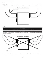
Page 31: ...ciones apropriada s para los soportes véase la ilustración a continuación según la posición de los montantes Inserte los soportes suministrados debajo del cuadro del aparato véase la ilustración a la derecha Use el tornillo n o 8 x 3 8 pulg para fijar el soporte Usando los 4 tornillos suministrados n o 8 x 1 pulg sujete el aparato en la pared asegurándose de que los 4 tornillos queden sujetos en u...

Page 32: ...esitan al menos un registro de salida en el nivel más alto Aire fresco hacia el edificio Instale registros en dormitorios comedor sala de estar y sótano Instale los registros en el techo O en la parte alta de las paredes de modo que la corriente de aire vaya dirigida hacia el techo Si hay que instalar un registro en el suelo dirija la corriente de aire hacia la parte superior de la pared VH0162 No...

Page 33: ... auto balanceo del aparato consulte la sección 5 2 Aire fresco del exterior Aire viciado hacia el exterior Aire viciado del edificio Aire fresco hacia el edificio VH0168 Instalación alternativa T 5 No se puede utilizar el modo recirculación con esta configuración El aparato debe sincronizarse con el funcionamiento del sistema central de aire forzado para evitar condensación y crecimiento del moho ...

Page 34: ... al desagüe del suelo a otro conducto de desagüe o a un balde IMPORTANTE Si utiliza un balde para recoger el agua sitúe el extremo del conducto a 1 pulg aproximadamente de la parte superior del balde para evitar que el agua retroceda al aparato VO0290E 13 pulg 330 mm 13 pulg 330 mm VO0083E 1 pulg TIRA DE AMARRE 2 pulg Para los aparatos configurados a 110 pi3 min o menos si lo desea puede usar un k...

Page 35: ... moho Nunca use tornillos para conectar conductos a los puertos con el fin de no perturbar el funcionamiento de las compuertas situadas dentro de los puertos Una compuerta que no funciona podría congelar el aparato lo que podría provocar roturas PRECAUCIÓN VJ0157 2 5 Instalación de las bocas exterioras Para evitar toda contaminación Mantener una distancia de al menos 10 pies entre ambas bocas O us...

Page 36: ...iado aplastados De lo contrario la precisión de los flujos de aire será afectada PRECAUCIÓN IMPORTANTE Asegúrese de conectar los conductos como se ilustra a continuación para obtener una lectura precisa de los flujos de aire Una instalación correcta también permitirá un drenaje adecuado del agua que se pueda acumular en los conductos R 3 pulg mínimo NOTA Instalar los conductos lo más recto posible...

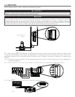
Page 37: ...ez conectado el control o controles murales introduzca el conector de terminales en el compartimento eléctrico No instale nunca más de un control mural principal opcional por aparato Compruebe que los cables no se cortocircuiten entre ellos o tocando otros componentes del control mural Evite las malas conexiones del cableado Para reducir el riesgo de interferencia eléctrica ruido no pase los cable...

Page 38: ...el aparato está desbalanceado ya que la distribución de aire está constante a pesar de una mayor exigencia en ventilación a la salida NOTA Se puede utilizar el control mural auxiliar con una conexión a 3 cables eliminando los indicadores LED Este cableado opcional no permitirá una instalación con más de un control mural auxiliar para sincronizar correctamente sus indicadores LED para un evento req...

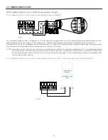
Page 39: ... G R C Acc Acc Termostato del sistema central de aire forzado Sistema central de aire forzado Cableado con conexión de contacto seco 1 1 External switch or any Dry contact can be used to activate Vent input if not available on the Thermostat Cableado alternativo para una instalación independiente de contacto seco Vent Y W C Gf G R J13 OVR LED 12V D D GND J9 Interruptor exterior o cualquier contact...

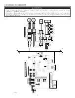
Page 40: ...A aislado OVR LED 12V D D GND Cableado de los controles principales y auxiliares Termistor R1 RT 1 NTC Puente IPM Motor 1 IPM Motor 1 F3 F2 M2 To J3 F5 F4 sistema central de aire forzado Relé K1 PTC3 Converti dor aislado 12VDC 3 3 VDC J9 J13 Función lógica 3 3 VDC PTC2 To J9 12VDC M4 To J6 M5 Motor de pasos To J7 PTC6 PTC4 To J13 R TH 1 To J7a R1 LCD Conjunto Tierra aislada Masa digital To J15a A2...

Page 41: ...CONFIGURACIÓN DE OPCIÓN UTILIZAR EL BOTÓN PARA DESPLAZARSE HACIA ARRIBA EN LAS OPCIONES DISPONIBLES O EL BOTÓN PARA DESPLAZARSE HACIA ABAJO EN LAS OPCIONES DISPONIBLES UNA VEZ LA SELECCIÓN DE OPCIÓN HECHA PRESIONAR EL BOTÓN OK PARA CONFIRMAR LA SELECCIÓN LA PRÓXIMA CONFIGURACIÓN DE OPCIÓN APARECERÁ PRESIONAR EL BOTÓN OK DURANTE 4 SEGUNDOS PARA CAMBIAR LA CONFIGURACIÓN DEL PI 3 MIN MÍNIMO LOS DATOS...

Page 42: ...in mínimo aparecerá en la pantalla LCD Utilizar para ajustar el pi3 min y OK para confirmar La casa que parpadea en la pantalla LCD indica qué lado limita el flujo de aire aire fresco o aire viciado Si el flujo de aire alcanzado no es suficiente el instalador puede mejorar la instalación para aumentar el flujo de aire Selección de la configuración de instalación INS aparecerá en la pantalla LCD El...

Page 43: ... la configuración y o la instalación del aparato el aparato podría no ser capaz de alcanzar el pi3 min mínimo deseado Esta situación se puede producir con las configuraciones T 2 a T 5 En tal caso AHUXX XX hace referencia al pi3 min mínimo deseado aparecerá en la pantalla LCD En modo AHU el aparato funciona en modo intermitente para alcanzar el pi3 min mínimo deseado La duración del modo intermite...

Page 44: ...rador CE con termistor SV66149 1 1 Bolsa de piezas SV66146 1 1 1 1 1 1 1 1 1 Fusible para la tarjeta electrónica SV66147 1 1 1 1 1 1 1 1 1 Conducto pulg SV00592 1 1 1 1 1 1 1 1 1 No se muestra VL0086 B C D E F G H I J K L B110H65RT B110H65RS B130H65RT B130H65RS B130E65RT B130E65RS B160H65RT B160H65RS B160E65RT B160E65RS B160H75RT B160H75RS B160E75RT B160E75RS B150H75NT B150H75NS B150E75NT B150E75N...

Page 45: ...66144 07 X SV66144 08 X SV66144 09 X SV66144 10 X SV66144 11 X SV66144 12 X SV66144 13 X SV66144 14 X SV66144 15 X SV66144 16 X SV66144 17 X SV66144 18 X B110H65RS B110H65RT B130H65RS B130H65RT B160H65RS B160H65RT B150H75NS B150H75NT B160H75RS B160H75RT B130E65RS B130E65RT B160E65RS B160E65RT B150E75NS B150E75NT B160E75RS B160E75RT 7 PIEZAS DE RECAMBIO cont ...

Page 46: ... el compartimento eléctrico verificar si el conector J6 azul está bien insertado verificar si hay cables sueltos Si la ETAPA 2 no arregló el problema realizar la ETAPA 3 Si la compuerta no se mueve desenchufar J5 blanco de la tarjeta electrónica conectar el conector azul del sistema de compuertas en J5 Si la compuerta mueve el sistema sigue indicando un error reemplazar el conjunto electrónico Si ...

Page 47: ...no arregló el problema realizar la ETAPA 2 Reemplazar el conjunto electrónico E35 Motor a la salida subtensión motor E36 Motor a la salida sobrecalentamiento motor ETAPA 1 Validar si el intercambiador de aire es expuesto a temperaturas ambiente dentro de los límites de funcionamiento ver p 4 Si la ETAPA 1 no arregló el problema realizar la ETAPA 2 Reemplazar el conjunto electrónico E40 Termistor a...

Page 48: ... realizar la ETAPA 2 Retirar los conductos de la línea de alimentatión En la pantalla LCD seleccionar MAX para verificar si el aparato puede lograr el flujo seleccionado En caso de que así sea verificar la línea de los conductos Si la ETAPA 2 no arregló el problema realizar la ETAPA 3 En la pantalla LCD seleccionar los valores de ajuste de los flujos MIN y MAX y después reinicializar el aparato El...

Page 49: ... control mural principal opcional Selector de velocidad Dehumidostato o Automático presionar el botón INT AUTO durante 5 segundos para reinicializar los filtros Si utiliza el control mural principal opcional Avanzado siga las instrucciones en la pantalla táctil 9 MANTENIMIENTO PRECAUCIÓN Un orificio de ventilación o un filtro bloqueado aunque sólo sea parcialmente puede hacer que el aparato funcio...

Page 50: ...cto con el instalador 3 Condensación en las ventanas en caso de bajas temperaturas Haga funcionar el aparato a velocidad MAX durante las actividades que generan humedad excesiva reuniones familiares mucha cocina etc Deje las cortinas entreabiertas para que el aire circule Guarde toda la leña en un cuarto cerrado equipado con un deshumidificador en un cuarto bien ventilado o en el exterior Mantenga...

Page 51: ...ión Edificio Toda construcción usada o destinada para ser usada con el fin de alojar o recibir personas animales o cosas Uso residencial Vivienda alojamiento suite edificio o parte de un edificio que sirve o está destinado a servir de domicilio a una o varias personas y que también posee instalaciones sanitarias para preparar y consumir comidas y dormir Local constituido por una sola pieza o un gr...

Page 52: ...26 ...

Reviews: