


16
5.3 s
ettings
m
oDiFicAtion
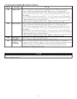
5.3.1 p
rocedure
To
m
odifY
min
cfm
s
eTTinG
•
Go to MIN using (+/-) then press on the OK button for 4 seconds.
•
Use (+/-) to increase/decrease CFM and OK to confirm.
5.3.2 p
rocedure
To
m
odifY
max
cfm
s
eTTinG
•
Go to MAX using (+/-) then press on the OK button for 4 seconds.
•
Use (+/-) to increase/decrease CFM and OK to confirm.
5.3.3 p
rocedure
To
m
odifY
o
pTions
s
eTTinG
•
Go to CFG OPT using (+/-) then press on the OK button for 4 seconds.
5.3.4 p
rocedure
To
m
odifY
i
ndependenT
a
irflows
s
eTTinG
•
Press simultaneously (+/-) buttons for 4 seconds.
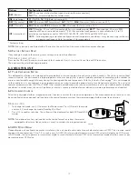
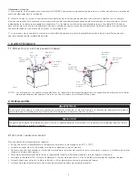
5.2 u
nit
F
irst
b
oot
p
reparaTion
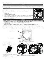
Follow these steps to ensure accurate measurements:
•
Seal all the ductwork with tape. Close all windows and doors.
•
Turn off all exhaust devices such as range hood, dryer and bathroom fans.
•
If the installation is in any way connected to a ductwork of a central forced-air system, make sure that the central forced-air system
blower is ON. If not, leave central forced-air system blower OFF.
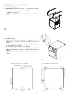
a
uTo
-b
alancinG
p
rocedure
•
Plug the unit and wait for the maximum CFM to display on the LCD screen. If unit is colder than ambient temperature, it is normal to
experience a 60 s longer boot-up since motors have to preheat.
•
The maximum CFM will display on the LCD screen. Use (+/-) to adjust the CFM and OK to confirm.
•
The minimum CFM will display on the LCD screen. Use (+/-) to adjust the CFM and OK to confirm.
•
The house that flashes on the LCD screen indicates which side currently limits the airflow (supply or exhaust). If the airflow reached is
not sufficient, the installer can improve the installation to increase airflow.
i
nsTallaTion
c
onfiGuraTion
s
elecTion
•
INS will display on the LCD screen. Choose among T-1, T-2, T-3, T-4 or T-5 following the installation configuration (Refer to section
2.2 for more details).
•
Auto-balancing is completed.
5.1 D
isplAy
on
lcD s
creen
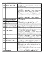
DISPLAY
DEFINITION
DISPLAY
DEFINITION
STB
Standby mode
OVR 60
Override 60 min
MED
MED speed
OVR CNT
Override by dry contact
INT
Intermittent mode
AHU
Refer to section 6.3 for explanation
REC
Recirculation mode
(Min, Med or Max speed)
HUM
Humidistat or Dehumidistat override
AUT
AUTO mode
TUR
Turbo mode
SMT
SMART mode
OTH
Away mode or Scheduling mode
OVR 20
Override 20 min
DEF
Defrost mode
OVR 40
Override 40 min
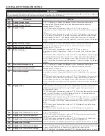
EXX or WXX
(XX referring to error or warning number)
Refer to section 8 for each error/warning explanation
VQ0217
VQ0218
VQ0219
VQ0220
+
+
-
-
OK
OK
OK
+
WHEN MAX DISPLAYS, PRESS ON
+
BUTTON TO EXIT INDEPENDENT
AIRFLOWS SETTING.
SUPPLY AIRFLOW VALUE WILL FLASH.
PRESS ON
+
BUTTON OR
-
BUTTON TO
INCREASE/DECREASE VALUE.
PRESS
OK
BUTTON.
EXHAUST AIRFLOW VALUE WILL FLASH.
PRESS ON
+
BUTTON OR
-
BUTTON TO
INCREASE/DECREASE VALUE.
PRESS
OK
BUTTON.