SA-SRVG8-20, SA-SRVG8-40
4
Security Analytics Gen14 Dell Server Quick Start Guide
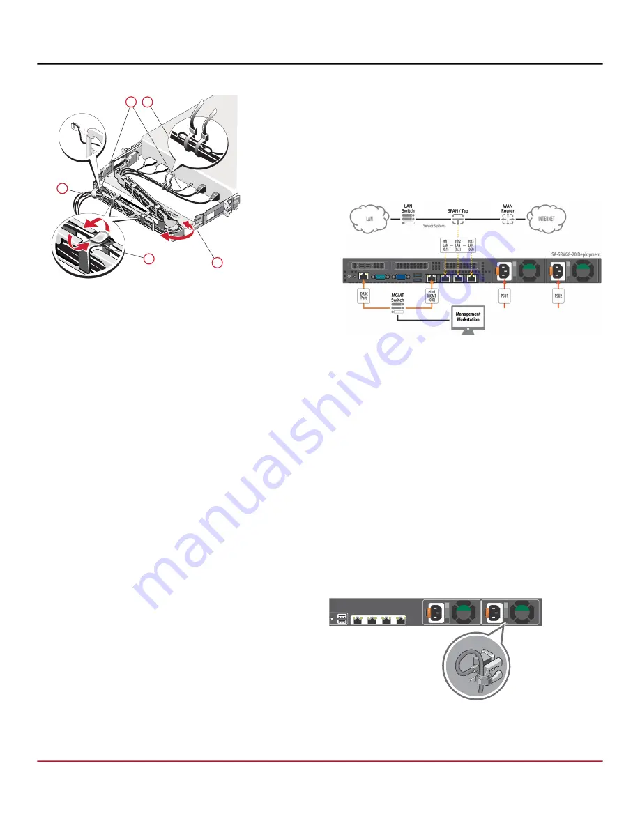
6. Cable the server using the CMA:
CAUTION!
To avoid potential damage from protruding
cables, secure any slack in the status indicator cable before
routing this cable through the CMA.
Using the tie wraps provided, bundle the cables
together as they enter and exit the baskets so they do
not interfere with adjacent servers (
1
).
With the CMA in the service position, route the cable
bundle through the inner and outer baskets (
2
).
Use the preinstalled Velcro straps on either end of the
baskets to secure the cables (
3
).
Swing the CMA back into place on the tray (
4
).
Install the status indicator cable at the back of the
server and secure the cable by routing it through the
CMA. Attach the other end of the cable to the corner of
the outer CMA basket (
5
).
4 — Connect Cables
The following deployment documents a single Security
Analytics server appliance. For information on other
deployments, including those with multiple servers or multiple
SPAN/TAP switches, see the Security Analytics documentation
at:
NOTE:
Network cables are not included with the server.
Make sure to use only straight-through Ethernet cables.
Category 5E cables or better are recommended for
1000Base-T operation. Category 6A cables are
recommended for 10GBase-T operation.
1. Connect a USB keyboard to the server’s front- or rear-
panel USB port.
2. Connect a VGA cable to the server’s front- or rear-panel
VGA port and connect the other end of the cable to a
VGA monitor. The VGA ports are not hot-pluggable.
3. Connect an Ethernet cable to the server’s
MGMT 0:0
port and connect the other end of the cable to the
management network switch or directly to a laptop.
4. Connect an Ethernet cable to the server’s
iDRAC
port
and connect the other end of the cable to the
management network switch.
5. If you are a deploying a Security Analytics Sensor
System, for capturing data, do the following:
For
SA-SRVG8-20
servers, connect Ethernet cables to the
server’s onboard LAN ports (0:1, 0:2, 0:3), from which you
will capture data. Connect the other ends of the cables to
the SPAN or TAP switch.
For
SA-SRVG8-40
servers, connect Ethernet cables to
the server’s LAN ports
(1:0, 1:1)
installed in PCIe slot 3,
from which you will capture data. Connect the other
ends of the cables to the SPAN or TAP switch.
6. Connect the included AC power cords to the server’s
power inlets and connect the other ends of the cables to
a power source.
7. Secure the power cables using the retention straps.
2
1
3
5
4


