background image

e-mail: 

[email protected]   

voice: 

360.854.9559   

fax: 

866.783.1742

8

Smart Relay 4 Installation and Operation Manual

INSTALLATION

Mode DIPswitch

Description

10

1010

Two input NOR (0 = input inactive, 1 = active)
00 1
01 0
10 0
11 0

11

1011

Two input OR
00 0
01 1
10 1
11 1

12

1100

Two input XOR
00 0
01 1
10 1
11 0

13

1101

Two input AND
00 0
01 0
10 0
11 1

14

1110

Two input NAND
00 1
01 1
10 1
11 0

15

1111

Reserved (feature creep).

Installation of the Smart Relay 4 in high RF environments should be performed with
care.  Shielded cable is suggested for all connections.  All shields should be tied to the
EGND terminals.  The station ground should be connected to the chassis ground screw
located on the far right side of the SR-4 as viewed from the rear.  It is recommended
that all cables connected to the SR-4 be looped through ferrite cores to suppress RF.
Surge protection with RF filtering is also suggested for the wall transformer.  The pur-
chase of an inexpensive UPS will provide back up in case of power outages.

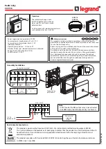
Connections are via screw terminals and/or the RJ-21X option.  Remove about 1/8”
of insulation from each wire.  Insert the wire into the desired terminal and tighten
the screw.  Be sure no bare wires are exposed.

! NOTE:

Refer to page 11 of this manual when using the RJ-21X option.

Summary of Contents for SR-4

Page 1: ...t Revisions of this information or new editions may be issued to incorporate such changes Broadcast Tools is a registered trademark of Broadcast Tools Inc Copyright 1989 2007 by Broadcast Tools Inc Al...

Page 2: ...p 3 Product Description 4 Features 4 Applications 4 Installation 5 Timing Programming 5 HyperTerminal Set up 5 Logic Programming 7 Input and Relay wiring 9 Input jumper set up 10 Slave Relay Set up 11...

Page 3: ...hardware software instruction manuals or contact the man ufacturers technical support department WHO TO CONTACT FOR HELP If you have any questions regarding your product or you need assistance please...

Page 4: ...t or 5 volt dry inputs LED indicators are provided for each relay power and programming Fifteen logic functions include sustained toggle set reset flip flop dual alter nate action or failing rising ed...

Page 5: ...led CONNECTION DESCRIPTION 2 In this window type a name that describes the connection We suggest SR 4 click the appropriate icon if desired and click OK 3 A new window will open labeled CONNECT TO 4 A...

Page 6: ...be displayed Timing Programming TIMER MENU HOURS MINUTES SECONDS 00 CH1 00 00 00 05 CH2 00 00 00 05 CH3 00 00 00 05 CH4 00 00 00 05 TO CHANGE SELECT 1 2 3 4 Each of the four channels can be programme...

Page 7: ...of the odd input Relay remains closed until the leading edge of the even input is active 3 0011 The relay closes after the odd input has been active for the programmed time period It opens after the e...

Page 8: ...ted for all connections All shields should be tied to the EGND terminals The station ground should be connected to the chassis ground screw located on the far right side of the SR 4 as viewed from the...

Page 9: ...opto isolator configuration header 1 Input 1A JP1 2 Input 1B JP1 3 Input 2A JP2 4 Input 2B JP2 5 Ground 6 Slave K1 relay input pull to ground to activate K1 7 K1A Normally Closed 8 K1A Common wiper 9...

Page 10: ...on informa tion The JP number in parentheses is the opto isolator configuration header 1 Input 7A JP7 2 Input 7B JP7 3 Input 8A JP8 4 Input 8B JP8 5 Ground 6 Slave K4 relay input pull to ground to act...

Page 11: ...from the same wall transformer by unitizing the supplied daisy chain cable The user may also power the SR 4 from the punch block if this option is employed RJ 21X option To install this option follow...

Page 12: ...ver connect 120 Vac cir cuits to these relays Connectors Screw terminals 2 1mm power jacks and or the RJ 21X punch block option Power Requirements 9 to 24 volts AC DC 200 ma 9 Vac 1 amp wall transform...

Page 13: ...O OTHER WARRANTIES OR REMEDIES TO THE MAXIMUM EXTENT PERMITTED BYAPPLICABLE LAW BROADCAST TOOLSAND ITS SUPPLIERS DISCLAIMALL OTHER WARRANTIES EITHER EXPRESS OR IMPLIED INCLUDING BUT NOT LIMITED TO IMP...

Page 14: ...______________ 37 12 Black Orange Ground 5 B ___________________________________ 12 Orange Black K2B N C 10 T ___________________________________ 38 13 Black Green Input 5B TB3 2 B ___________________...

Page 15: ...L3 7A 7B 8A 8B G SL4 NO COM NC NO COM NC K4B K4A NO COM NC NO COM NC K3B K3A NO COM NC NO COM NC K2B K2A NO COM NC NO COM NC K1B K1A Smart Relay 4 Input Relay and Jumper Layout e mail support broadcas...

Page 16: ...Fractional Schematic e mail support broadcasttools com voice 360 854 9559 fax 360 854 9479 16 Smart Relay 4 Installation and Operation Manual APPENDIX...

Page 17: ...e mail support broadcasttools com voice 360 854 9559 fax 360 854 9479 17 Smart Relay 4 Installation and Operation Manual APPENDIX...

Reviews: