e-mail:
voice:
360.854.9559
fax:
866.783.1742
8
DTD-16 + G2 Installation and Operation Manual
PROGRAMMING
Programming
The DTD can be programmed from a computer via it USB serial, or RS-232 serial
interfaces.
Connecting via the USB Serial “PGM” port:
1. Connect the supplied USB A/B cable from the “USB PGM” jack on the DTD rear
panel to an available USB port on your PC. When you first plug the DTD into
your PC, it should automatically install the correct FTDI USB Serial “Virtual
COM port” drivers which will allow you to access the DTD on a COM port.
NOTE: If the DTD’s FTDI USB Serial “Virtual COM port” drivers do not
automatically install they may be downloaded here:
http://www.ftdichip.com/Drivers/VCP.htm
2. Start a serial terminal application like PuTTY, Tera Term or HyperTerminal con-
figured for the connected COM port set to 9600 baud, 8, N, 1, flow control to
NONE, Emulation set to ANSI, and local character echo enabled.
Connecting via the RS-232 Serial “PGM” port:
1. Connect the supplied “S9” RJ11 to DB9 adapter cable from the RJ11 PGM jack
on the DTD rear panel to an available RS232 serial COM port on your PC.
2. Start a serial terminal application like PuTTY, Tera Term or HyperTerminal con-
figured for the connected COM port set to 9600 baud, 8, N, 1, flow control to
NONE, Emulation set to ANSI, and local character echo enabled.
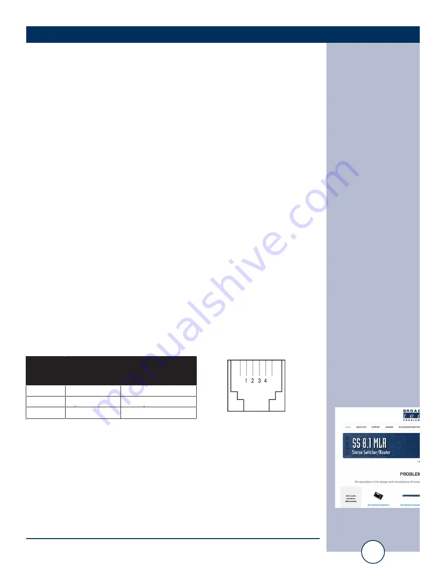
“S9” RJ11 to DB9 adapter pinout:
WEBSITE:
Visit our web site for
product updates and
additional information.
RJ-11
Adapter
Pin
DB-9 D-SUB
Pin #
4
3
RS-232 Receive
3
2
RS-232 Transmit
2
5
Ground
Product’s point of
view Function Name.
Modular Jack
Pin Numbers


