


BriskHeat
®
Corporation. All rights reserved
19
Centipede 2® Module™ Temperature Control System
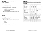
Appendix B: Centipede 2
®
Control Zone Register
Definitions
Register Description
Address
Memory
Access
Default Description
Firmware Revision
0
Flash
R
NA
Line Processor Revision
1
Flash
R
NA
Zone Status
2
Ram
R/W
NA
Sampled Temperature
3
Ram
R
NA
Deg c * 100
Controller Config Register
4
EEPROM
R/W
64
Temperature Setpoint
5
EEPROM
R/W
0
0.00 C
Temperature Hi Limit alarm
6
EEPROM
R/W
0
0.00 C
Temperature Lo Limit alarm
7
EEPROM
R/W
0
0.00 C
100 Ohm Calibration value hi
8
EEPROM
R
6800
Ohms * 100
100 Ohm Calibration value lo
9
EEPROM
R
6800
Ohms * 100
Reserved
10 - 12
NA
NA
NA
PID Pg Current value
13
Ram
R
NA
PID Pd Current value
14
Ram
R
NA
PID Pi Current value
15
Ram
R
NA
Current PWM percentage
16
Ram
R
NA
ADC Raw Data value
17
Ram
R
NA
Reserved
18 - 100
NA
NA
NA
BriskHeat
®
Corporation. All rights reserved
20
Centipede 2® Module™ Temperature Control System
Appendix C: OI Settings Setup: wr:10,"Value"
Register 10 of the Operator Interface is the “Settings” register. The Register consists of 16
bits and the register is defined below. The “Value” is the Decimal equivalent to the Binary
for the 16 bits.
Register 10 – Operator Interface Settings Register
Bits 15-0
Cs: Controller Settings
0:
ALARM RELAY CTRL – Actuate/de-actuate (1/0) relay when alarm active
1:
LOW TEMP LATCH – Set to enable latch of low temperature alarm
2:
HIGH TEMP LATCH – Set to enable latch of high temperature alarm
3:
OPEN RTD LATCH – Set to enable latch of open rtd alarm
4:
SHORT RTD LATCH – Set to enable latch of short rtd alarm
5:
NOT USED
6:
NOT USED
7:
PASSWORD ENABLE – Set to enable GUI password
8:
TIMER DISPLAY 12 HOURS – Display timer (GUI) in 12 hour mode (AM/PM)
9:
TEXT UI SESSION TIMEOUT DISABLE – Disables text ui session timeouts
14:
ALARM LOG CLEAR – Clear alarm history one-shot when set
15:
UNLATCH ALL ON-SHOT – Set to do a single unlatch of all latched alarms
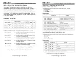
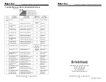
Example “Value” determination*:
In the above example Cs9 (Bit Pos. 9) is set to 1. This is translated to a decimal value as 1
* 2 ^ 9. And similarly Cs0 (Bit Pos.0) is set to 1. This is translated to a decimal value as 1
* 2 ^ 0. Other bits, such as Cs2 (Bit Pos. 2), as set to 0. This is translated to a decimal
value as 0 * 2 ^ 2. The sum of all of the decimal values is the final decimal number to use
for the command.
BH> wr:10,513
This command places the Operator Interface Register 10 bits such that Cs9 (Bit Pos. 9)
and Cs0 (Bit Pos. 0) are activated. All other bits are inactivated.
*Note: Microsoft Windows Operating Systems have a simple Calculator as part of their
suite of Accessories. That Calculator software includes a View -> Programmer setting,
where one can easily convert from binary to decimal and reverse.
Bit Position
15
14
13
12
11
10
9
8
7
6
5
4
3
2
1
0
Desired Binary Value
0
0
0
0
0
0
1
0
0
0
0
0
0
0
0
1
Value of Each Binary
Bit into Decimal
(Each Bit Base-2)
0
0
0
0
0
0
512
0
0
0
0
0
0
0
0
1
Sum of Decimal
Values
513
Entered Decimal
Value
513
Cs15
Cs14
Cs13
Cs12
Cs11
Cs10
Cs9
Cs8
Cs7
Cs6
Cs5
Cs4
Cs3
Cs2
Cs1
Cs0


