12
5HQRYHQW([FHOOHQW)
Chapter 5 Installation
5.5 Electric connections
5.5.2 Connecting the multiple switch
The multiple switch (not supplied with the appliance) is con-
nected to the modular connector type RJ12 (connector X2) that
is placed at the rear of the appliance's display cover.
Dependent on the type of multiple switch that is used, a plug
RJ11 or RJ12 can be connected to it.
$SSOLFDWLRQ RI D ZD\ VZLWFK ZLWK ¿OWHU LQGLFDWLRQ LQ DOO
cases requires an RJ12 plug in combination with a 6-core
modular cable.
$SSOLFDWLRQRIDZD\VZLWFKZLWKRXW¿OWHULQGLFDWLRQLQDOO
cases requires an RJ11 plug in combination with a 4-core
modular cable.
Refer to diagrams §11.2.1 to §11.2.4 for connection examples
multiple switch.
Other options include wireless remote control or a combination
of multiple switches.
The 4-way switch can also be used to activate a 30-minutes
boost mode by putting the switch to setting 3 for less than 2
seconds and directly turning it back to setting 1 or 2. The boost
mode can be reset by putting the switch to setting 3 for longer
than 2 seconds or by switching it to absence mode
(
).
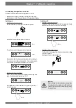
5.5.1 Connecting the power plug
The appliance can be connected to an easily accessible,
earthed wall socket with the plug that is mounted to the ap-
pliance. The electric installation must comply with the require-
ments of your power company.
Make allowance for the 1000 W preheater.
Warning
The fans and control board carry a high volt-
age. Always take the voltage from the appli-
ance by pulling the power plug when working
on the appliance.
5.5.3 Connecting eBus
The Renovent Excellent operate with eBus protocol. The set-
ting of parameter 08 in the settings menu (see chapter 13) lets
you choose between eBus and OpenTherm.
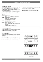
An eBus connection can be made with the 2-pole connector X1
at the rear of the display cover.
The eBus protocol can for instance be used for coupling (cas-
cade control) appliances (see §11.3). Because of polarity sen-
sitivity, always connect contacts X1-1 to X1-1 and contacts
X1-2 to X1-2 ; the appliance will not work when these contacts
DUHLQWHUFKDQJHG
RJ12
X1
A
A Cables to be connected by installer
(minimum wire diameter 0.34 mm
2
)
The optionally available control unit must be connec-
ted to this connector eBUS.
nr.1
nr.2
X1
Summary of Contents for Renovent Excellent 450
Page 1: ...Renovent Excellent 450 Plus WWW BRINKAIRFORLIFE NL 614784 F INSTALLATION INSTRUCTIONS English ...
Page 2: ......
Page 8: ... 5HQRYHQW FHOOHQW ...
Page 45: ......


