Pa
g
e
1
1
LEVEL ADJUSTMENT
Adjust the length of the top link so that the
machine is parallel (front to rear) to the ground
surface when operating at the desired depth.
TURNING
The machine should always be raised com-
pletely out of the ground when turning. This
will relieve stress on the shanks, mounting
hardware, and machine frame.
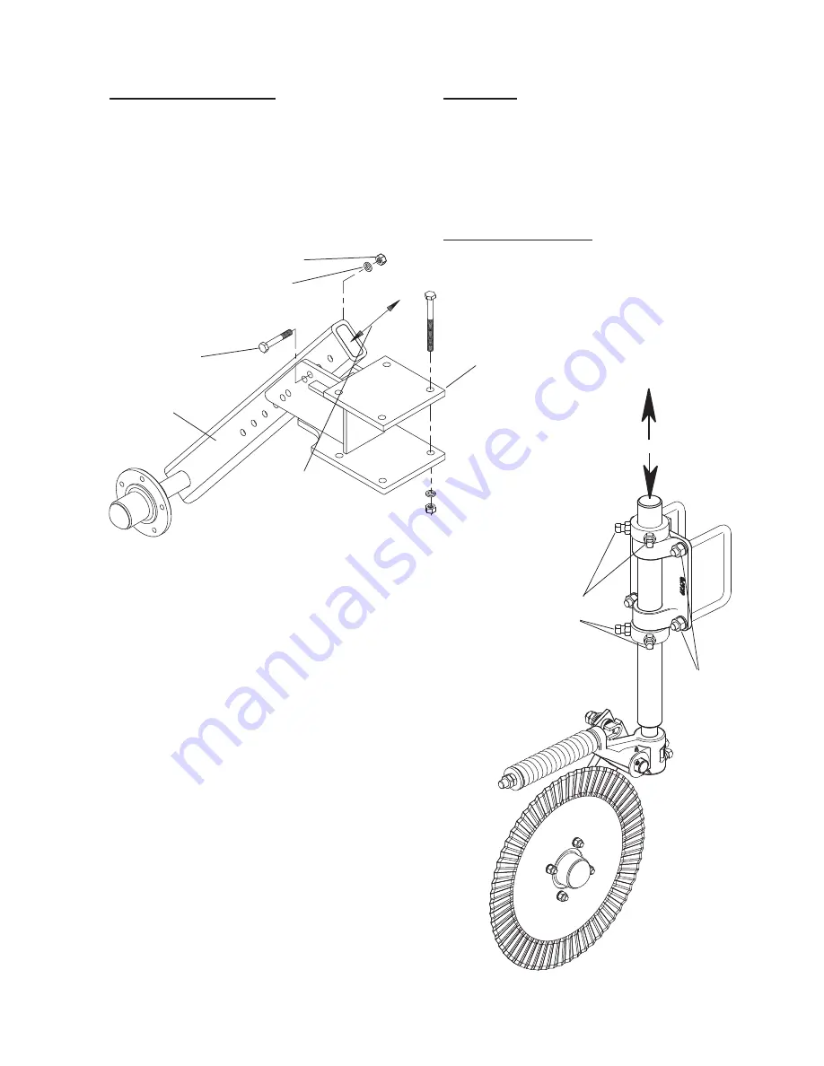
DEPTH CONTROL of SHANKS
Adjust the height of the manual
gauge wheel by removing the
bolts and sliding the gauge wheel
arm to the desired position within
the mount. Replace the bolts and
tighten before operating. See
Figure 4.
Manual Gauge Wheel
DEPTH CONTROL of
COULTER
ASSEMBLY
After the desired depth of the shanks have
been set, changes to the working depth of the
coulter blades can be made. Simply lower the
assembly by loosening the locking nuts and set
screws which hold the shaft. Adjust to desired
depth, make sure that the coulter stop is facing
forward to allow the coulter arm to swing side to
side. See Figure 7.
Tighten the set screws and the locking nuts.
LOCKWASHER, 5/8”
LOCK NUT, 5/8-11NC
HHCS, 5/8-11
NC X 9 1/2”
MOUNT
GAGE WHEEL
ADJUST HEIGHT
LOCK NUT
5/8-11
ADJUST HEIGHT
SET SCREWS
COULTER ASSEMBLY
Figure 4a
Figure 4b
9K308
604
Page 9
Summary of Contents for Compaction Commander 03 Series
Page 2: ...Page 2 9K308 604 Page 1...
Page 4: ...Page 4...
Page 25: ...Page 25 CCD5243 CCD5303 Figure 16e Figure 16f 30 0 30 30 30 48 24 48 0 24 9K308 604 Page 23...
Page 28: ...Page 28 72 96 72 48 48 96 0 24 24 CCD9243 Figure 16j 9K308 604 Page 26...
Page 29: ...Page 29 9K308 604rev10 4 05 Page 27 This Page Left Blank Intentionally...
Page 33: ......


