background image

Not for 

Reproduction

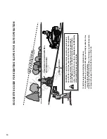
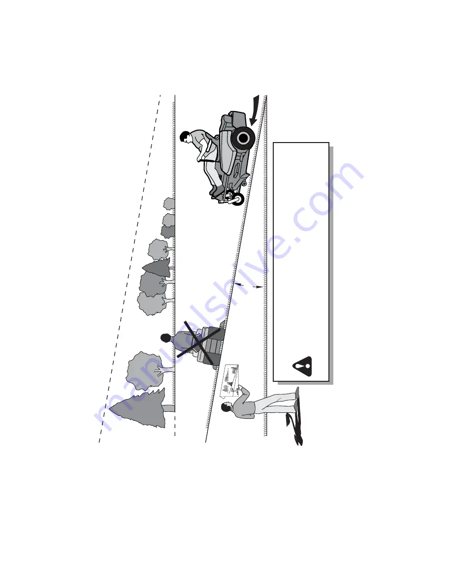
WARNING: To avoid serious injury, operate your unit up and 

down the face of slopes, never across the face. Do not operate 

on slopes greater


than

 10 degrees. Make turns gradually to 

prevent tipping or loss of control. Exercise extreme caution 

when changing direction on slopes. 

Braking may be affected by 

attachments. Reduce speed on slopes.

1. Fold this page along dotted line indicated above.

2. Hold page before you so that its left edge is vertically parallel to a tree  


trunk or other upright structure.

3. Sight across the fold in the direction of hill slope you want to measure.

4. Compare the angle of the fold with the slope of the hill.

ONLY RIDE UP AND DOWN HILL,

NOT ACROSS HILL

F

O

L

D

 A

LON

G

 D

OT

TED LI

N

E

THIS IS 

A

 10 DEGREE 

S

LOPE

10 DEGREES MAX.

SUGGESTED GUIDE FOR SIGHTING SLOPES FOR SAFE OPERATION

10  

Summary of Contents for Zero Turn Rider

Page 1: ...N o t f o r R e p r o d u c t i o n Zero Turn Rider 1757570 Revision B ...

Page 2: ...N o t f o r R e p r o d u c t i o n Copyright 2013 Briggs Stratton Power Products Group LLC Milwaukee WI USA All rights reserved 2 ...

Page 3: ...shooting the Mower 32 Specifications 33 Operator Safety 4 Safety Interlock System Tests 12 Features and Controls 13 Control Functions 13 Operation 15 General Operating Safety 15 Checks Before Starting 15 Starting the Engine 16 Stopping the Rider and Engine 16 Mowing 16 Pushing the Rider by Hand 16 Zero Turn Driving Practice 17 Attaching a Trailer 19 Maintenance 20 Maintenance Chart 20 Checking Tir...

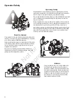
Page 4: ...done with the equipment you have chosen ask a professional contact your local authorized dealer Read the Manual The operator s manual contains important safety infor mation you need to be aware of BEFORE you operate your unit as well as DURING operation Safe operating techniques an explanation of the prod uct s features and controls and maintenance informa tion is included to help you get the most...

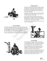
Page 5: ...s can pick up and throw debris that could seriously injure a bystander Be sure to clean up the area to be mowed and remove objects that could be thrown by the blade BEFORE you start mowing Do not operate this unit without the entire grass catcher or discharge guard deflector in place Also do not allow anyone in the area while the unit is running If some one does enter the area shut the unit off im...

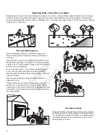
Page 6: ...o the safety and perfor mance of your unit Keep the unit free of grass leaves and excess oil Be sure to perform the maintenance proce dures listed in this manual especially periodically testing the safety system Retaining Walls Drop Offs and Water Retaining walls and drop offs around steps and water are a common hazard Give yourself a minimum of two mower widths of clearance around these hazards a...

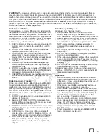
Page 7: ...hine on slopes exceeding 10 degrees 18 grade 2 Exercise EXTREME CAUTION on all slopes Turn blades OFF when traveling uphill Use a slow speed and avoid sudden or sharp turns 3 DO NOT operate machine back and forth across face of slopes Operate up and down Practice on slopes with blades off 4 AVOID starting stopping or turning on slopes If machine stops going uphill or tires lose traction turn blade...

Page 8: ...medi ately 11 Never overfill a fuel tank Replace fuel cap and tigh ten securely OPERATION 1 Mount and dismount machine from left side Keep clear of discharge opening at all times 2 Start engine from operator s seat if possible Make sure blades are OFF and parking brake is set 3 DO NOT leave machine with engine running STOP engine STOP blades SET brake and Remove key before leaving operators positi...

Page 9: ...g engine could cause injury 8 DO NOT work under machine without safety blocks 9 Service engine and make adjustments only when engine is stopped Remove spark plug wire s from spark plug s and secure wire s away from spark plug s 10 DO NOT change engine governor speed settings or overspeed engine 11 Lubricate machine at intervals specified in manual to prevent controls from binding 12 Mower blades a...

Page 10: ...ed by attachments Reduce speed on slopes 1 Fold this page along dotted line indicated above 2 Hold page before you so that its left edge is vertically parallel to a tree trunk or other upright structure 3 Sight across the fold in the direction of hill slope you want to measure 4 Compare the angle of the fold with the slope of the hill ONLY RIDE UP AND DOWN HILL NOT ACROSS HILL F O L D A L O N G D ...

Page 11: ...lace them at once See your local dealer for replacements These decals are easily applied and will act as a con stant visual reminder to you and others who may use the equipment to follow the safety instructions necessary for safe effective operation Decal Warning Part No 1755607 Decal Warning Part No 1755608 Decal Danger Part No 1755606 Decal Danger Part No 7101665 DANGER Amputation and thrown obj...

Page 12: ... is engaged AND Ground speed levers are locked into their START PARK positions Test 3 Engine should SHUT OFF if Operator rises off seat with PTO engaged OR Operator rises off seat with parking brake dis enaged OR Operator rises off seat with ground speed levers not locked in their START PARK positions Test 4 Check mower blade stopping time The mower blades and mower drive belt should come to a com...

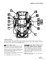
Page 13: ...ons Engine Speed Choke Control Briggs Stratton Engines Move the engine speed choke control to the FAST position to increase engine speed and to the SLOW position to decrease engine speed Move the engine speed choke control past the FAST position to the CHOKE position to start a cold engine A warm engine may not require choking NOTE Always operate the rider with the engine speed control in the FAST...

Page 14: ...the RUN posi tion with the engine stopped this drains the battery PTO Switch The PTO Power Take Off switch engages and disengages the mower blade clutch To engage the PTO pull UP on the switch Push DOWN to disengage Note that the operator must be seated firmly in the rider seat for the PTO to function Transmission Release Levers The transmission release levers deactivate the transmissions so that ...

Page 15: ...he engine rider and mower free of grass leaves and excess grease Do not stop or park rider over dry leaves grass or combustible materials Gasoline is highly flammable and must be handled with care Never fill the tank when the engine is still hot from recent operation Do not allow open flame smoking or matches in the area Avoid over filling and wipe up any spills WARNING Never operate on slopes gre...

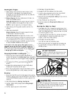
Page 16: ...4 Move the engine speed control to the SLOW position and turn the ignition key to OFF Remove the key Mowing 1 Make sure the PTO switch is disengaged the parking brake is engaged the ground speed levers are locked in their START PARK positions and the operator is in the seat 2 Start the engine see Starting the Engine 3 Set the mower cutting height see Cutting Height Adjustment 4 Set the engine spee...

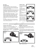
Page 17: ...om neutral Slow down and repeat Practice backing up for several minutes before attempt ing to do so near objects The rider turns as sharply in reverse as when going forward and backing up straight takes practice Zero Turn Driving Practice The ground speed levers of the zero turn rider are responsive and learning to gain a smooth and efficient control of the rider s forward reverse and turning move...

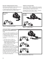
Page 18: ...amiliar and experi enced with operating the zero turn rider you will learn more maneuvers that will make your mowing time easier and more enjoyable Remember the more you practice the better your control of the rider will be Executing Turns Figure 6 Turning Around a Corner Figure 7 Turning in Place Turning In Place Figure 8 Executing an End Of Row Turn Practice Turning In Place To turn in place zer...

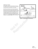
Page 19: ...ause loss of traction and loss of control on slopes Reduce towed weight when operating on slopes The surface being driven on greatly impacts traction and stability Wet or slippery surfaces can greatly reduce traction and the ability to stop or turn Carefully evaluate the surface conditions before oper ating the unit and trailer and never operate on slopes greater than 10 See Protection Against Tip...

Page 20: ...bles Check mower blades ENGINE First 5 Hours Change engine oil Every 8 Hours or Daily Check engine oil level Every 25 Hours or Annually Clean engine air filter and pre cleaner Every 50 Hours or Annually Change engine oil Replace oil filter Annually Replace air filter Replace pre cleaner See Dealer Annually to Inspect muffler and spark arrester Replace spark plug Replace fuel filter Clean engine ai...

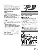
Page 21: ...3 Using pliers open and slide hose clamps from fuel filter A Figure 11 4 Remove hoses from filter 5 Install new filter in proper flow direction in fuel line 6 Secure with hose clamps 7 Reconnect the negative battery cable when finished Engine Maintenance Refer to engine manual for all engine maintenance pro cedures and recommendations WARNING Gasoline is highly flammable and must be handled with c...

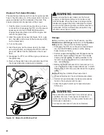
Page 22: ...the mower must be in the operator position and there must be no bystanders Failure to follow these precautions may result in serious injury or death Figure 12 Mower Deck Washout Port B A C Storage Before you store your unit for the off season read the Maintenance and Storage instructions in the Operator Safety section then perform the following steps Disengage the PTO move the ground speed levers ...

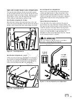
Page 23: ...d speed levers are in the maximum forward position the top speed of each of these levers can be balanced Only adjust the speed of the wheel that is traveling faster Loosen the bolt securing the forward adjust plate see Figure 16 Slide the plate up approximately 1 8 Retighten the bolt and recheck speed balance Repeat steps until adjustment is complete Seat and Ground Speed Lever Adjustments The sea...

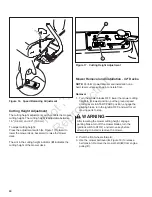
Page 24: ...t Mower Removal and Installation 42 Decks NOTE Perform mower removal and installation on a hard level surface such as a concrete floor Removal 1 Turn the mower blades OFF lower the mower cutting height to its lowest position put the ground speed control levers in START PARK position engage the parking brake turn the ignition OFF and wait for all moving parts to stop 2 Pivot the front wheels forwar...

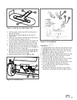
Page 25: ... Separate the front hitch rods from the mower deck 11 Slide the mower deck out from under the rider C B A Figure 19 Front Lift Arms A B Figure 20 Rear Lift Arms B A C C Installation 1 Slide the mower deck under the right side of the rider 2 Slide the mower deck forward and connect the front hitch rods C Figure 19 to the mower deck Secure with washers B and hair pin clips A 3 Slide the mower deck b...

Page 26: ... from under the unit Figure 21 Mower Belt Routing C A B Figure 22 Rear Deck Lift Components Right side shown left side same Installation 1 Disengage the PTO engage the parking brake lock the ground speed levers into their START PARK posi tions turn off the ignition remove the key and wait for all moving parts to stop 2 Lower the mower deck to its lowest position see Cutting Height Adjustment 3 Piv...

Page 27: ...ide See Figure 24 2 Measure the distance between the two outside blade tips A B Figure 24 and the floor The difference between the two measurements A B should be less than 1 8 3mm 6 If adjustment is needed tighten the nuts C D on the right or left side of the deck until the correct mea surement is achieved Figure 24 Mower Deck Leveling Side to Side 1 8 3 mm 9 16 9 16 A B WARNING After adjusting th...

Page 28: ...B Figures 25 26 turn the nuts D then C Figure 26 in the direction indi cated until the correct measurement is achieved To lower the front blade tip B Figures 25 27 turn the nuts C then D Figure 27 in the direction indi cated until the correct measurement is achieved NOTE Be sure to turn the nuts on both sides the same amount of turns Figure 25 Mower Deck Level Check Front to Back Figure 26 Raising...

Page 29: ...reattach the battery cables positive cable first B 4 Coat the cable ends and battery terminals with petro leum jelly or non conducting grease 5 Be sure to replace the terminal cover C over the positive battery terminal Battery Charging A dead battery or one too weak to start the engine may be the result of a problem in the charging system or other electrical component If there is any doubt about t...

Page 30: ...ble ends and battery terminals with petro leum jelly or non conducting grease 5 Be sure to replace the terminal cover B over the positive battery terminal Battery Charging A dead battery or one too weak to start the engine may be the result of a defect in the charging system or other electrical component If there is any doubt about the cause of the problem see your dealer To charge the battery fol...

Page 31: ...or replace See engine manual Water in fuel Drain fuel and refill with fresh fuel Circuit breaker blown See authorized service dealer Engine starts hard or runs poorly Fuel mixture too rich Clean air filter Check the choke Spark plug faulty fouled or incorrectly gapped Clean and gap or replace See engine manual Fuel filter dirty Replace fuel filter Engine knocks Low oil level Check add oil as requi...

Page 32: ...uthorized service dealer Mower drive belt slipping because it is oily or worn See authorized service dealer Blades not properly fastened to spindles See authorized service dealer Engine stalls easily with mower engaged Engine speed too slow Set engine speed control to FAST Ground speed too fast Decrease ground speed Cutting height set too low Cut tall grass at maximum cutting height during first p...

Page 33: ...ng Procedure and is rated in accordance with SAE J1995 Torque values are derived at 2600 RPM for those engines with rpm called out on the label and 3060 RPM for all others horsepower values are derived at 3600 RPM The gross power curves can be viewed at www BRIGGSandSTRATTON COM Net power values are taken with exhaust and air cleaner installed whereas gross power values are collected without these...

Page 34: ...N o t f o r R e p r o d u c t i o n 34 Notes ...

Page 35: ...N o t f o r R e p r o d u c t i o n 35 en Notes ...

Page 36: ...N o t f o r R e p r o d u c t i o n ...

Reviews: