Briggs & Stratton Massey Ferguson 2690477 Adjustment Instructions Manual Download Page 11

Not for 

Reproduction

11

Simplicity / Massey Ferguson / Snapper ZTR

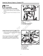
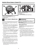
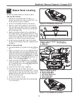
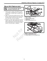
Figure 15.  Neutral Adjustment
A.  Control Rod Spring
B.  Rod End

Return-To-Neutral & 
Neutral Adjustment

RETURN-TO-NEUTRAL ADJUSTMENT

To determine if it is necessary to adjust the neutral 
return, perform the following steps.

 1.  Disengage the PTO, engage the parking brake and 

turn off the engine.

 2.  Move the ground speed control levers into the operat-

ing position, pull levers rearward and release.

 3.  Move the ground speed control levers out towards 

the neutral position.  If the levers do not align with the 
notches in the neutral lock plate, it is necessary to 
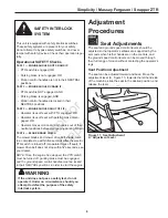
adjust the neutral return rod (C, Figure 14).

TO ADJUST:

 1.  Loosen the jam nut (B) locked against the clevis (A).

 2.  Turn the neutral return rod (C) to adjust handle posi-

tion.

 4.  Pull lever rearward and release to check position 

again.  Adjust as necessary to align levers with 
notches.

It is important to note that after every adjustment of the 
neutral return rod, the lever must be pulled rearward and 
released to properly check the neutral position.

 5.  Once the lever alignment has been adjusted, lock 

jam nut against the clevis.

NEUTRAL ADJUSTMENT

If the tractor creeps while the ground speed control 
levers are locked in neutral, then it may be necessary to 
adjust the linkage rods.  

Perform this adjustment on a hard level surface such as 
a concrete floor.

IMPORTANT NOTE: This adjustment should be per-
formed with the engine OFF.  Perform the adjustment, 
then start the engine to check the adjustment.  If further 
adjustment is required, stop the engine before adjusting 
the linkage.

 1.  Determine which wheel is creeping.  The left side 

hydro pump and control linkage control the left wheel, 
the right linkage controls the right wheel.

 2.  Disengage the PTO, engage the parking brake, turn 

the engine off, remove the key, and wait for all mov-
ing parts to stop.

 3.  Check the control rod spring (A, Figure 15) length.  

The compressed spring length should be 2-3/16” 
(5,56 cm)

 4.  Disconnect the rod end (B) and loosen the jam nut.  

Turn the rod end one to two turns to lengthen or 
shorten the control rod, then retighten the jam nut, 
and reconnect the rod end.

B

A

 5.  Start the unit and check for transmission creep.  

Repeat steps 2-4 if necessary.

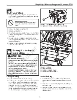
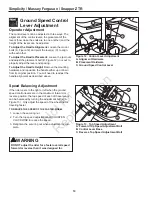
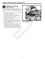
Figure 14.  Return-To-Neutral Adjustment
A. Clevis
B.  Jam Nut
C.  Neutral Return Rod

A

B

C

Summary of Contents for Massey Ferguson 2690477

Page 1: ...uded with the unit contain important information that must be obeyed when assembling setting up operating servicing trans porting or storing the unit These warnings are highlighted by the safety alert triangle sym bol shown above which signifies that an important safety mes sage is being provided You must read understand and follow these warnings and instructions and use safe shop and work practic...

Page 2: ...o Reduce check tire pressures Front tires 40 psi rear tires 15 psi 7 Mower Assembly o Torque mower blade bolts 7 Lubrication o Lubricate all grease oil points 8 SAFETY CHECKS o Check for loose hardware o Check all OPERATOR CONTROLS o Test PARKING BRAKE o Perform Mower Blade Stopping Check Blade must stop within 5 seconds o Perform Safety Interlock System Check 8 Burnish Electric Clutch o Burnish e...

Page 3: ...safety rules section of this document Charge the battery until fully charged until the specific gravity of the electrolyte is 1 250 or higher and the electrolyte temperature is at least 60 F Do not charge at a rate higher than 10 amps WARNING BATTERY SAFETY RULES Battery acid causes severe burns Avoid contact with skin Wear eye protection while handling the battery To avoid an explosion keep flame...

Page 4: ...Plate C 5 16 18 Nylock Flange Nut 4 D Seat Switch Wire Harness FRONT FRONT A B C D E Figure 4 Install Control Levers A 5 16 18 x 1 Bolts B 5 16 Lockwashers C 5 16 Washers D Control Lever E Control Lever Base Install Ground Speed Control Levers 1 Mount the control levers F Figure 4 to the control lever base E using four 5 16 18 x 1 bolts lockwash ers and washers NOTE The ground speed control levers...

Page 5: ...ure 6 If the oil is below this level proceed to step 2 2 Before removing the reservoir cap make sure the area around the reservoir cap and fill neck of the res ervoir is free of dust dirt or other debris Loosen the locking capscrew E Figure 5 securing the locking tab D slide the lock tab back and remove the cap B 3 Add oil up to the full mark A Figure 6 4 Reinstall the reservoir cap move the locki...

Page 6: ...Remove the engine guard hardware B Figure 8 from the upper tank support bracket of the unit 2 Loosely install the engine guard A as shown in Figure 8 The bolt should be installed from ther rear of the machine through the washer the engine guard the upper tank support bracket the tank bracket and then secured with the nylock flange nut 3 Push the fuel tanks in towards the center of the machine befo...

Page 7: ...9 Blade Installation A 4x4 Wood Block B Hex Washer 44 50 Models Only C Spring Washer D Blade Capscrew Figure 10 Lubrication Lube Idler Arm Pivot Generally all moving metal parts should be oiled where contact is made with other parts Keep oil and grease off belts and pulleys Remember to wipe fittings and sur faces clean both before and after lubrication Use grease fittings when present Disassemble ...

Page 8: ...ic PTO clutch switch and wait several seconds Disengage electric clutch switch and check the time it takes for the mower drive belt to stop If the mower drive belt does not stop within five seconds adjust the PTO clutch according to the instructions in the Electric Clutch Adjustment sec tion Seat Switch Connection Check that the seat switch wire harness D Figure 2 is connected to the seat switch B...

Page 9: ...R Motion control handles are not in their NEUTRAL positions Test 2 Engine SHOULD crank if PTO switch is NOT engaged AND Parking brake is engaged AND Motion control handles are locked in their NEUTRAL positions Test 3 Engine should SHUT OFF if Operator rises off seat with PTO engaged OR Operator rises off seat with parking brake disen gaged OR Operator moves motion control handles out of their neut...

Page 10: ... You will need to readjust the handle alignment as described above Speed Balancing Adjustment If the rider veers to the right or left when the ground speed control levers are in the maximum forward or reverse position the top speed of each of these levers can be balanced by turning the adjustment bolt s A Figure 13 Only adjust the speed of the wheel that is traveling faster To Reduce the Speed of ...

Page 11: ...l position 5 Once the lever alignment has been adjusted lock jam nut against the clevis NEUTRAL ADJUSTMENT If the tractor creeps while the ground speed control levers are locked in neutral then it may be necessary to adjust the linkage rods Perform this adjustment on a hard level surface such as a concrete floor IMPORTANT NOTE This adjustment should be per formed with the engine OFF Perform the ad...

Page 12: ...pring A Figure 16 length both wheels With the brake engaged the compressed spring length should be 2 5 cm If not adjust the locknut C to achieve the compressed spring length of 2 5 cm 3 After achieving the correct spring compression check the set collar gap B With the parking brake engaged the set collar gap should be 3 16 5 mm If not loosen the set collar screw and move the collar to the correct ...

Page 13: ...d greater stability on hilly terrain To adjust the spring pre load 1 Park machine on a flat level surface Disengage the PTO stop the engine and engage the parking brake 2 See Figure 17 Turn the pre load adjustment collar A CLOCKWISE to increase the pre load turn COUNTER CLOCKWISE to decrease the pre load Make sure both front shocks are set to the same amount of pre load Make sure both rear shocks ...

Page 14: ...nuts B Figure 18 until the rotor face and armature face just contacts the gauge 5 Check the windows for an equal amount of tension when the gauge is inserted and removed and make any necessary adjustments by tightening or loosen ing the adjustment nuts NOTE The actual air gap between the rotor and arma ture may vary even after performing the adjustment pro cedure This is due to dimensional variati...

Page 15: ... back Figure 23 7 Measure the distance from the ground to the front tip of the center blade and from the ground to rear tips of left hand and right hand blades Figures 21 23 The front tip of the center blade should be 1 4 6mm higher than rear tips of left hand and right hand blades If not proceed with steps 8 11 8 Check the length of the hanging rods The rear D Figure 22 should be 15 38 1 cm and i...

Page 16: ...such as a concrete floor Turn the front wheels so they are straight 3 Place the mower cutting height pin in the 4th hole from the bottom C Figure 24 4 Measure the distance between the outside ends of the roller bar and the ground If there is more than 1 8 3mm difference between the measurements on each side proceed to step 5 5 Locate the roller bar leveling eccentric and locknuts A Figure 24 Loose...

Page 17: ... tighten 3 4 of a turn more NOTE The oil will drain from the reservoir tank if the new filter is not quickly reinstalled 5 Run the unit for several minutes and check the trans mission oil level B IMPORTANT NOTE Use caution after changing the filter air in the hydraulic system may affect the responsiveness of the control levers Repeat step 5 until the air is out of the system Do not allow dirt wate...

Page 18: ...and remove the nut to completely release the tension 4 Remove the old belt and replace it with the new one Make sure the V side of the belt runs in the grooves of the crankshaft pulley and pump pulleys B C 5 Reinstall the anchor hook H into the anchor tab and loosely fasten the nut Adjust the spring until a measurement of 7 3 4 19 7 cm is achieved from the outside of the spring hooks Tighten nut 6...

Page 19: ... mower belt Secure the lever in the guard notch B if equipped 3 Remove the old drive belt and install the new one as shown in Figure 28 Note that the back of the drive belt must ride against the back side idler pulleys B Use the belt tension lever A Figure 29 to release tension on the idler pulley for installation To avoid damaging belts do not pry belts over pulleys Figure 28 Mower Belt Routing A...

Page 20: ...om PRODUCTS INC 535 Macon Street McDonough GA 30253 www snapper com Briggs Stratton Power Products Group LLC Copyright 2013 Briggs Stratton Corporation Milwaukee WI USA All rights reserved The Simplicity logo is a trademark of Briggs Stratton Corporation Milwaukee WI USA The Snapper logo is a trademark of Briggs Stratton Corporation Milwaukee WI USA ...

Reviews: