background image

Not for 

Reproduction

1.

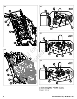
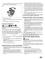
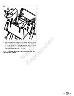
Remove the 1/4-28 bolt (B, Figure 18) screwed into the front
caster and install a 1/4-28 grease fitting.

18

2.

Grease the front caster.

3.

Remove the 1/4-28 grease fitting and re-install the 1/4-28
bolt.

4.

Repeat process for the other side of the machine.

Checking / Adding Fuel

WARNING

Fuel and its vapors are extremely flammable and
explosive.

Fire or explosion can cause severve burns or death.

Gasoline is highly flammable and must be handled with care.
Never fill the tank when the engine is still hot from recent
operation. Do NOT allow open flame, smoking or matches in
the area. Avoid over-filling and wipe up any spills.

To add fuel:

1.

Stop the engine and allow it to cool for at least 3 minutes.

2.

Remove the fuel cap.

3.

Fill the tank to the bottom of the filler neck. This will allow
for fuel expansion.
NOTE: Do not overfill. Refer to your engine manual for
specific fuel recommendations.

4.

Install and hand tighten the fuel cap.

Starting the Engine - Manual Start Models

1.

Engage the parking brake and make sure the PTO switch
is disengaged and the forward speed control lever is in the
NEUTRAL position.

2.

Set the engine throttle control to FULL throttle position.
Then fully close the choke by pulling the knob OUT fully.
NOTE: A warm engine may not require choking.

3.

Insert the key into the ignition switch and turn it to the RUN
position.

4.

Grasp the recoil starter handle and pull slowly until
resistance is felt and then pull rapidly. You may have to pull
several times before the engine starts. If the engine fails to
start within a reasonable number of attempts, discontinue
and check engine operator's manual for further instructions.

5.

After the engine starts, gradually open the choke (push
knob down fully). Reduce to half throttle speed and allow
to warm up. Warm up the engine by running it for at least
a minute before engaging the PTO switch or driving the
mower.

6.

After warming the engine, ALWAYS operate the unit at
FULL THROTTLE when mowing.

In the event of an emergency the engine can be stopped
by simply turning the ignition switch to STOP.

Starting the Engine - Electric Start Models

1.

Engage the parking brake and make sure the PTO switch
is disengaged and the forward speed control lever is in the
NEUTRAL position.

2.

Set the engine throttle control to FULL throttle position.
Then fully close the choke by pulling the knob OUT fully.
NOTE: A warm engine may not require choking.

3.

Insert the key into the ignition switch and turn it to the
START position.

4.

After the engine starts, gradually open the choke (push
knob down fully). Reduce to half throttle speed and allow
to warm up. Warm up the engine by running it for at least
a minute before engaging the PTO switch or driving the
mower.

5.

After warming the engine, ALWAYS operate the unit at
FULL THROTTLE when mowing.

In the event of an emergency the engine can be stopped
by simply turning the ignition switch to STOP.

Perform the Safety Checks

WARNING

Disengage the PTO, stop the engine, set the parking brake,
and wait for moving parts to stop before leaving the operator’s
position for any reason.

If the unit does not pass a test, do not operate the unit. Under
no circumstance should you attempt to defeat the purpose of
the safety system.

Functional Tests

1.

Check the unit for loose bolts, screws, nuts, etc.

2.

Start the engine and check all the controls for proper
operation: ground speed control levers, parking brake,
throttle cable, electric PTO clutch, etc.

3.

Stop the engine and check for fluid leaks: oil, fuel, and
hydraulic oil.

9

Summary of Contents for FW25 series

Page 1: ...N o t f o r R e p r o d u c t i o n ...

Page 2: ... LOOSE HARDWARE Check all OPERATOR CONTROLS Perform SAFETY INTERLOCK SYSTEM CHECK Register Product To register the product log onto www thepowerportal com select the appropriate brand click My Resources select the Product Registration and Rebate icon and then the New Product Registration Rebate tab Fill out and submit the online product registration form FERRIS and SNAPPER PRO are registered trade...

Page 3: ...rward and inward to release them from the disengaged position and then allow them to move forward to the engaged drive position B Connect the Battery Cables to the Battery Electric Start Models Only WARNING Battery acid can cause severe burns Wear protective gear when handling the battery Open flames and sparks can cause battery to explode BATTERY SAFETY RULES Battery acid causes severe burns Avoi...

Page 4: ...system If the unit is not driving properly perform the Purging the Air from the Hydraulic System procedure Check Tire Pressures Tire pressure should be checked periodically and maintained at the levels shown in the chart Note that these pressures may differ slightly from the Max Inflation stamped on the side wall of the tires The pressures shown in the chart provide proper traction and extend tire...

Page 5: ...ng position and remove the mower deck guards 3 36 Mower Decks Make sure that the V side of the mower deck drive belt B Figure 6 runs in the pulley grooves of the spindle pulleys D and the pulley grooves of the PTO clutch pulley and that the back side of the belt contacts the rear stationary pulley C and the adjustable idler pulley E 36 Mower Decks 6 48 52 Mower Decks Make sure that the V side of t...

Page 6: ...belt exerted from the idler arm 5 Re seat the mower deck drive belt and carefully release the tension on the breaker bar Check Adjust the Mower Belt Idler Tensioning Spring Length Mower Deck Belt Idler Tensioning Spring Length Measurement Serial Number Deck Size 6 3 4 17 1 cm 2017555756 Below 36 Mower Deck 7 17 8 cm 2017555757 Above 36 Mower Deck 6 1 8 15 6 cm All 48 Mower Deck 6 3 4 17 1 cm 20172...

Page 7: ...axle Drive Idler Arm B 3 2 Mower Deck Spindles A Figures 15 16 17 1 Mower Deck Idler Arm B 48 Models Units in serial number range 2017170234 below only 52 Models Units is serial number range 2017243270 below only 2 Front Caster Wheel Axles See Lubricating the Front Casters A Figure 18 N A Front Casters See Lubricating the Front Casters Not all greases are compatible Red grease p n 5022285 is recom...

Page 8: ...N o t f o r R e p r o d u c t i o n 13 14 15 16 17 Lubricating the Front Casters Interval Annually 8 ferrismowers com snapperpro com ...

Page 9: ...tructions 5 After the engine starts gradually open the choke push knob down fully Reduce to half throttle speed and allow to warm up Warm up the engine by running it for at least a minute before engaging the PTO switch or driving the mower 6 After warming the engine ALWAYS operate the unit at FULL THROTTLE when mowing In the event of an emergency the engine can be stopped by simply turning the ign...

Page 10: ...models Mower blades and mower drive belt should come to a complete stop within seven 7 seconds after electric PTO switch is turned OFF or operator releases the operator presence handles If the mower drive belt does not stop within seven 7 seconds see your dealer Note Once the engine has been stopped the forward speed control lever must be returned to the NEUTRAL position the parking brake should b...

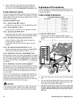
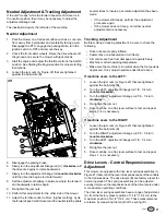
Page 11: ...further neutral adjustments are necessary Tracking Adjustment Before making a tracking adjustment be sure to check the following Drive tires are properly inflated Caster tires are lubricated and turn freely All controls are free from damage and operate freely Machine is at full operating temperature Make sure the machine is in neutral when the foot pedal is depressed If not adjust neutral as descr...

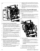
Page 12: ...tment knob counter clockwise until the desired level of responsiveness is achieved 4 Measure the length C of the spring D and record this measurement This measurement should not be longer than 7 1 4 18 4 cm 5 Tighten the wing nut against the black adjustment knob 6 Repeat this process for the other side of the mower The measurements for both drive lever spring assemblies must be the same Drive Lev...

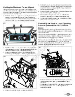
Page 13: ... preferred maximum forward speed 6 Position the bolt so that it contacts the forward speed control lever and then tighten both jam nuts 7 Return the forward speed control lever to the Neutral position by depressing the neutral return pedals fully 8 Tilt the front handle bar guard back into place and tighten the hardware to secure it in place Forward Speed Control Lever Operating Force Adjustment S...

Page 14: ... process detailed above but with the unit s drive wheels on the ground The procedure should be performed in an area free of any objects or bystanders It may be necessary to repeat the process detailed above until all the air is completely purged from the system When the transaxles transmissions operate at normal noise levels and move smoothly forward and reverse at normal speeds then the transaxle...

Page 15: ...t edge of the lower parking brake shaft plate C Figure 26 and the top of the set collars D The measurement should be 15 16 2 4 cm E If not position the set collars until the measurement equals 15 16 2 4 cm Note If this does not correct your braking problem see your authorized dealer 15 ...

Page 16: ...N o t f o r R e p r o d u c t i o n ...

Reviews: