


Not for
Reproduction
4.
If any control fails to operate properly during testing or
seems to be out of adjustment, check and re-adjust it
according to the following
Adjustment Procedures section.
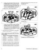
Safety Interlock System
This unit is equipped with safety interlock switches. These safety
systems are present for your safety, do not attempt to bypass
safety switches, and never tamper with safety devices. Check
their operation regularly.
Operational SAFETY Checks
Test 1 - Engine should NOT crank if:
• Forward speed control lever is not in the NEUTRAL position.
Test 2 - Engine SHOULD crank if:
• Forward speed control lever is in the NEUTRAL position.
Test 3 - Engine should SHUT OFF if:
• Operator releases the operator presence handles while the
forward speed control lever is not in the NEUTRAL position.
Test 4 - PTO Switch (blades) should SHUT OFF if:
• If the PTO switch is ON and the operator releases the
operator presence handles, OR
• The operator presses the PTO switch down to the OFF
position.
Test 5 - PTO Switch (blades) SHOULD turn on if:
• Operator depresses the operator presence handles and the
PTO switch is pulled up to the ON position.
Test 6 - Blade Brake Check (For model 5901441 only):
Mower blades and mower drive belt should come to a complete
stop within five (5) seconds after electric PTO switch is turned
OFF (or operator releases the operator presence handles). If
the mower drive belt does not stop within five (5) seconds, see
your dealer.
Test 6 - Blade Brake Check (For all other models):
Mower blades and mower drive belt should come to a complete
stop within seven (7) seconds after electric PTO switch is turned
OFF (or operator releases the operator presence handles). If
the mower drive belt does not stop within seven (7) seconds,
see your dealer.
Note: Once the engine has been stopped, the forward speed
control lever must be returned to the NEUTRAL position, the
parking brake should be engaged, the operator presence
handles should be depressed and the PTO switch should be in
the OFF position in order to start the engine.
WARNING
If the unit does not pass a safety test, do NOT operate it. See
your authorized dealer. Under no circumstance should you
attempt to defeat the purpose of the safety interlock system.
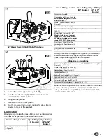
Adjustment Procedures
If any control fails to operate properly during testing or seems
to be out of adjustment, check and re-adjust it according to the
following instructions.
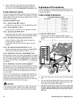
Cutting Height Adjustment
Cut Height Indication Chart
Cutting Height
Hole Number
1.5" (3,8 cm)
1
2.0" (5,1 cm)
2
2.5" (6,4 cm)
3
3.0" (7,6 cm)
4
3.5" (8,9 cm)
5
4.0" (10,2 cm)
6
4.5" (11,4 cm)
7
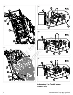
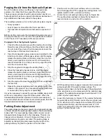
To adjust the cutting height:
1.
Use Figure 19 and the Cut Height Indication Chart to
determine the correct mounting holes for the desired cutting
height.
19
2.
Remove the hair pins (A, Figure 19) from the deck lift shafts
(C).
3.
Use the deck handle (B) and either raise or lower the cutter
deck to the desired cutting height. Re-install the hair pins
in the hole for the desired cutting height.
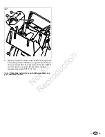
4.
Repeat the process for the other side of the machine. The
hair pins must be installed in the same numbered hole
in all four deck lift shafts for the mower deck to have a
level cut.
10


