48
MekFarmer 170
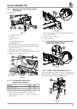
i = tractor’s wheelbase
d = horizontal distance between the center of gravity of the
front ballast and the tractor’s front axle
s = horizontal distance between the center of gravity of the
machine and the tractor’s rear axle
T = weight of the tractor in running order
Z = ballast weight
M = weight of the machine
0,2 T
T
Z
d
i
s
M
FIG. 30
5.6.8 SETTING WORKING DEPTH
DANGER
Park the machine on a horizontal and stable surface.
Disconnect PTO. Turn off the tractor. Put the parking
brake on.
NOTE
CHANGING THE POSITION OF THE REAR ROLLER IMPLIES A
NEW ADJUSTEMENT OF THE LEVELLING BAR.
The adjustment of the machine working depth depends on
the position of the rear roller.
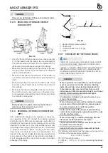
Setting with side pins
This solution (“Fig. 31”), not only permits depth adjust
-
ment, but also having a floating rear roller (ideal when the
-
re are stones). When the roller is lowered, working depth
decreases.
1
2
FIG. 31
The machine is on the ground. The roller arm is between
the pins (1) and (2).
To lower the roller and reduce the working depth:
•
Remove the pin (2).
•
Activate the machine power-lift and lift the machine.
•
Move pin (2) into the lowest hole.
•
Move pin (1) into the lowest hole.
To lift the roller and increase the working depth:
•
Remove the pin (1).
•
Activate the tractor power-lift and lower the machine.
The roller holder arm goes up.
•
Move pin (1) into the highest hole.
•
Move pin (2) into the highest hole: the roller must not
swing too much when operating.
•
Lock the pins: insert the retainer into the nearest hole.
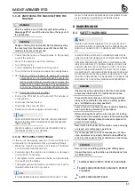
Setting with screw jacks (OPT)
This solution (“Fig. 32”) requires two screw jacks at the
ends of the machine and adjustable by means of a gradua
-
ted rod. When the roller is raised, working depth increases.
When the roller is lowered, working depth decreases
FIG. 32
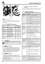
Setting with hydraulic cylinders (OPT)
This solution (“Fig. 33”) for adjusting work depth with hy
-
draulic control cylinders can be implemented from the
driving seat, by means of the hydraulic mechanism which
controls the two hydraulic cylinders that regulate the rear
rollers (8 Fig. 1) thus determining the work depth. Both hy
-
draulic cylinders feature stop valves. When the roller is rai
-
sed, working depth increases. When the roller is lowered,
working depth decreases.


