Assembly Instructions
/
Parts List
/
Troubleshooting
/
FAQ
/
Tips
/
Warranty
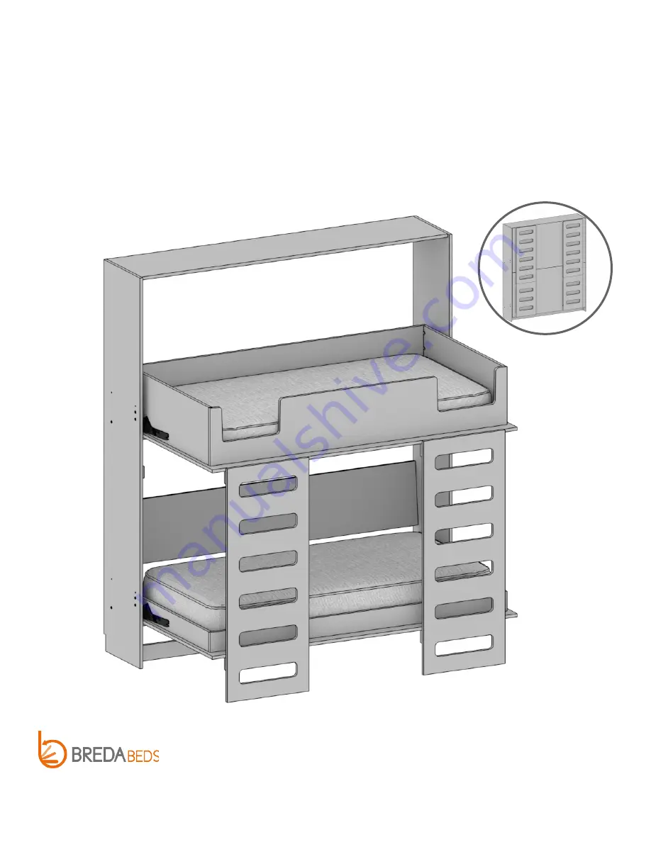
URBAN STACK
BUNK BED
Web:
https://bredabeds.com
Email:
[email protected]
Telephone:
1-855-466-4781
REVISION: H|3.9
URB-SB
OCTOBER 2022
3318 West Nelis Drive
Meridian, ID 83646


