background image

10 

COMBUSTIBLE WALL CHIMNEY CONNECTOR PASS-THROUGHS

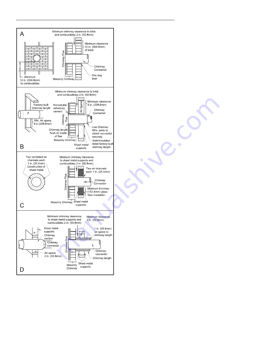
Method A. 12” (304.8 mm) Clearance to Combustible Wall Member: 

Using a minimum thickness 3.5” (89 mm) brick and a 5/8” (15.9 mm) 
minimum wall thickness clay liner, construct a wall pass-through.  The clay 
liner must conform to ASTM C315 (Standard Speci

fi

 cation for Clay Fire 

Linings) or its equivalent. Keep a minimum of 12” (304.8 mm) of brick 
masonry between the clay liner and wall combustibles.  The clay liner 
shall run from the brick masonry outer surface to the inner surface of the 
chimney 

fl

 ue liner but not past the inner surface.  Firmly grout or cement 

the clay liner in place to the chimney 

fl

 ue liner.  

Method B. 9” (228.6 mm) Clearance to Combustible Wall Member: Using 

a 6” (152.4 mm) inside diameter, listed, factory-built Solid-Pak chimney 
section with insulation of 1” (25.4 mm) or more, build a wall pass-through 
with a minimum 9” (228.6 mm) air space between the outer wall of the 
chimney length and wall combustibles.  Use sheet metal supports fastened 
securely to wall surfaces on all sides, to maintain the 9” (228.6 mm) air 
space.  When fastening supports to chimney length, do not penetrate the 
chimney liner (the inside wall of the Solid-Pak chimney).  The inner end of 
the Solid-Pak chimney section shall be 

fl

 ush with the inside of the masonry 

chimney 

fl

 ue, and sealed with a non-water soluble refractory cement.  Use 

this cement to also seal to the brick masonry penetration.

Method C. 6” (152.4 mm) Clearance to Combustible Wall Member: 

Starting with a minimum 24 gauge (.024” [.61 mm]) 6” (152.4 mm) metal 
chimney connector, and a minimum 24 gauge ventilated wall thimble which 
has two air channels of 1” (25.4 mm) each, construct a wall pass-through. 
There shall be a minimum 6” (152.4) mm separation area containing 

fi

 berglass insulation, from the outer surface of the wall thimble to wall 

combustibles.  Support the wall thimble, and cover its opening with a 
24-gauge minimum sheet metal support. Maintain the 6” (152.4 mm) space.  
There should also be a support sized to 

fi

 t and hold the metal chimney 

connector. See that the supports are fastened securely to wall surfaces on 
all sides.  Make sure fasteners used to secure the metal chimney connector 
do not penetrate chimney 

fl

 ue liner.  

Method D.  2” (50.8 mm) Clearance to Combustible Wall Member: Start 

with a solid-pak listed factory built chimney section at least 12” (304 mm) 
long, with insulation of 1” (25.4 mm) or more, and an inside diameter of 8” 
(2 inches [51 mm] larger than the 6” [152.4 mm] chimney connector). Use 
this as a pass-through for a minimum 24-gauge single wall steel chimney 
connector. Keep solid-pak section concentric with and spaced 1” (25.4 
mm) off the chimney connector by way of sheet metal support plates at 
both ends of chimney section.  Cover opening with and support chimney 
section on both sides with 24 gauge minimum sheet metal supports. See 
that the supports are fastened securely to wall surfaces on all sides. Make 
sure fasteners used to secure chimney 

fl

 ue do not penetrate 

fl

 ue liner.

NOTES:
 Connectors to a masonry chimney, excepting method B, shall extend in one continuous section through the wall pass-through 

system and the chimney wall, to but not past the inner 

fl

 ue liner face.

 A chimney connector shall not pass through an attic or roof space, closet or similar concealed space, or a 

fl

 oor, or ceiling.

Summary of Contents for SPC50

Page 1: ...available for download from the Breckwell website http www Breckwell com La version française est disponible pour téléchargement à partir du site Breckwell http www breckwell com MODEL SPC50 OWNER S OPERATION AND INSTALLATION MANUAL Part No 852202 Rev A Breckwell 227 Industrial Park Rd P O Box 151 South Pittsburg TN 37380 Phone 866 606 8444 or 800 750 2723 www Breckwell com This unit is not intend...

Page 2: ...ng door open A safety concern may arise from sparks or fumes entering the room Allow the stove to cool before performing any maintenance or cleaning Ashes must be disposed in a metal container with a tight fitting lid The closed container of ashes should be placed on a non combustible surface or on the ground well away from all combustible materials pending final disposal The exhaust system should...

Page 3: ...result in reduced performance and excessive cleaning requirements of your appliance and flue Store your pellets in a dry place DO NOT store the fuel within the installation clearances of the unit or within the space required for refueling and ash removal Doing so could result in a house fire Do not overfire or use volatile fuels or combustibles Doing so may cause personal and property damage hazar...

Page 4: ...TOVE INSTALLATION A stove must never be installed in a hallway or near a staircase since it may block the way in case of fire or fail to respect required clearances It is of the utmost importance that the clearances to combustible materials be strictly adhered to during installation of the stove Refer to the table and diagrams below for minimum required clearances Any reduction in clearance to com...

Page 5: ...y detailed installation requirements mobile home installations must meet the following requirements 1 The heater must be permanently attached to the floor 2 The heater must be electrically grounded to the steel chassis of the mobile home with 8 GA copper wire using a serrated or star washer to penetrate paint or protective coating to ensure grounding 3 When moving your mobile home all exterior ven...

Page 6: ... out when opened or back drafts occur whether or not there is combustion present 3 Opening a window slightly on a calm windless day alleviates any of the above symptoms 4 The house is equipped with a well sealed vapor barrier and tight fitting windows and or has any powered devices that exhaust house air 5 There is excessive condensation on windows in the winter 6 A ventilation system is installed...

Page 7: ...ion toward the chimney Any installation with a horizontal run of stove pipe must conform to NFPA 211 You may contact NFPA National Fire Protection Association and request the latest edition of the NFPA Standard 211 To insure a good draft the total length of the stove pipe should never exceed 8 to 10 2 4m to 3 04 m Except for cases of vertical installation cathedral roof style where the smoke exhau...

Page 8: ...aust above the outside air inlet elevation The termination must not be located where it will become plugged by snow or other materials DO NOT CONNECT THIS UNIT TO A CHIMNEY FLUE SERVING ANOTHER APPLIANCE The following recommendations may be useful for the installation of your chimney It must rise above the roof at least 3 0 9m from the uppermost point of contact The exterior portion should be doub...

Page 9: ...y a professional Make sure there are no cracks loose mortar or other signs of deterioration and blockage Have the chimney cleaned before the stove is installed and operated When connecting the stove through a combustible wall to a masonry chimney special methods are needed as explained in the Combustible Wall Chimney Connector Pass Throughs Section ...

Page 10: ...ector and a minimum 24 gauge ventilated wall thimble which has two air channels of 1 25 4 mm each construct a wall pass through There shall be a minimum 6 152 4 mm separation area containing fiberglass insulation from the outer surface of the wall thimble to wall combustibles Support the wall thimble and cover its opening with a 24 gauge minimum sheet metal support Maintain the 6 152 4 mm space Th...

Page 11: ...same manufacturer and install the ceiling support package or wall pass through and T section package firestops where needed insulation shield roof flashing chimney cap etc Maintain proper clearance to the structure as recommended by the manufacturer The chimney must be the required height above the roof or other obstructions for safety and proper draft operation ...

Page 12: ... heat the heat level will go to the level that you set on the controller It is recommended that you set the heat level to slightly above what is needed When the thermostat is satisfied then the stove will return to idle until heat is called for again TO ADJUST THE THERMOSTAT IDLE HEAT LEVEL 1 When the stove is in run mode scroll through the main menu until you see set idle heat level 2 Press enter...

Page 13: ...llet PRE START UP CHECK Clean the firebox Clean door glass if necessary a dry cloth or paper towel is usually sufficient Never use abrasive cleaners on the glass or door Check fuel in the hopper and refill if necessary It is recommended that you preform a system sensor check prior to initial and seasonal start up see trouble shooting BUILDING A FIRE Never use a grate or other means of supporting t...

Page 14: ... out REFUELING The hopper and stove top will be hot during operation therefore you should always use some type of hand protection when refueling your stove Never place your hand near the auger while the stove is in operation We recommend that you not let the hopper drop below full KEEP HOPPER LID CLOSED AT ALL TIMES EXCEPT WHEN REFILLING DO NOT OVERFILL HOPPER SHUTDOWN PROCEDURE If you must shutdo...

Page 15: ...qualified chimney sweep can perform this service It is also recommended that before each heating season the entire system be professionally inspected cleaned and if necessary repaired To clean the chimney disconnect the vent from the stove Establish a routine for the fuel wood burner and firing technique Check daily for creosote build up until experience shows how often you need to clean to be saf...

Page 16: ...controls on and make sure that they are working properly This is also a good time to give the entire stove a good cleaning throughout SPRING SHUTDOWN After the last burn in the spring remove any remaining pellets from the hopper and the auger feed system Scoop out the pellets and then run the auger until the hopper is empty and pellets stop flowing this can be done by pressing the ON button with t...

Page 17: ...UBLE SHOOTING GUIDE SYSTEM SENSOR CHECK PROCEDURE To preform a system sensor check the stove must be plugged in cool and off 1 Turn the stove on After a few seconds the controller will ask a series of questions Answer the questions as shown to proceed with the system check 2 Q1 Is there a fire in the burnpot A1 No press the left or down arrow key 3 Q2 Do you want to start a fire A2 No press the le...

Page 18: ...ent characteristics when being burned AUGER Auger jam Start by emptying the hopper Then remove the auger motor remove the auger shaft inspection plate in the hopper so that you can see the auger shaft After you have removed the shaft inspect it for bent flights burrs or broken welds Remove any foreign material that might have caused the jam Also check the auger tube for signs of damage such as bur...

Page 19: ...rent going to the fuel sensor thermodisc after the stove has been on for 10 minutes The proof of fire Fuel sensor thermodisc has came upluged Check the Fuel sensor thermodisc to see if the wires are connected properly The proof of fire Fuel sensor thermodisc has malfunctioned TemporarilybypasstheFuelsensorthermodiscbydisconnecting the two wires and connecting them with a short piece of wire Then p...

Page 20: ... or vent pipe is dirty which restricts airflow through the burnpot Follow all cleaning procedure in the maintenance section of the owner s manual COMBUSTION AIR The air inlet or the interior chambers have a partial blockage Follow all cleaning procedures in the maintenance section of the owner s manual Blockage in air intake pipe Visually inspect the air intake pipe that leads into the burnpot for...

Page 21: ...ot sending power to combustion blower If there is no current going to the combustion blower check all wire connections If all wires are properly connected you have a bad control board 9 Air switch has failed To test the air switch you will need to disconnect the air hose from the body of the stove With the other end still attached to the air switch very gently blow on the loose end of the hose you...

Page 22: ...ger Body 1 892322 Auger 1 892320 Auger Bushing Bearing Assembly 1 40602 Baffles 2 892314 Primary Secondary Air Tube Assembly 1 892315 Tube Weldment 1 892316 Primary Air Bushing 1 892317 Primary Air Nozzle 1 892318 Air Shutter Assembly 1 892313 Touchup Paint Specify Color 1 80664 4 Fan 2 80665 Electromagnet 12 Volt 1 80491 Microswitch 1 80661 Pressure Switch 1 80663 Hopper Thermodisc 1 80462 Recept...

Page 23: ...23 WIRING DIAGRAM J8 ...

Page 24: ...24 NOTES ...

Page 25: ...25 NOTES ...

Page 26: ...eplate attached to the heater When ordering repair parts always give the following information as shown in this list HOW TO ORDER REPAIR PARTS 1 The part number 2 The part description 3 The model number ________________________________________ 4 The serial number _________________________________________ Breckwell 227 Industrial Park Rd P O Box 151 South Pittsburg TN 37380 Phone 866 606 8444 www B...

Page 27: ..._______ Reason for Purchase Alternative Heat Main Heat Source Decoration Cost Other _________________________ What was the determining factor for purchasing your new appliance _______ I have read the owner s manual that accompanies this unit and fully understand the Installation Operation and Maintenance of my new appliance Print Name Signature Date Please attach a copy of your purchase receipt Wa...

Page 28: ...28 CUT HERE CUT HERE Fold Here Fold Here Fold Here PLACE STAMP HERE Breckwell 227 Industrial Park Rd P O Box 151 South Pittsburg TN 37380 USA ...

Reviews: