background image

32

SPECIFICATIONS

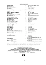
Supply Voltage

-

100 - 240 V alternating current

Supply Frequency

-

47 - 63 Hz

Maximum Input Current

-

0.40 – 1.0 Amperes

Fuse Ratings

-

2 x T 1.6 A 20mm

Dimensions (mm)

Length


-


297 

Width


- 223

Height


- 132

Weight

-

4.5 kg

Ambient Operating Temperature

-

32o C 90oF Max

Digital Output

-

RS232 Isolated to 1500 Volts

All displayed readings expressed as

-

ATPD

Max. Output Pressure

-

30cm H2O(44cm fault condition)

Calibrated pressure Range

-

0 - 30cm H2O

Accuracy of pressure reading

-

+/- 3.0% F.S. +/-1% zero

Max. Output Flow

-

200 L/min. (unrestricted)

Max Volume Reading

-

2000 millilitres

Accuracy of volume reading

-

Estimated

Accuracy of Flow reading

-

+/-10%

Inspiratory Trigger

-

0.14 – 2.21 L/sec

2

Expiratory Trigger

-

0.28 – 1.67 L/sec

2

Low Flow Alarm

-

0 – 160 lpm

High Flow Alarm

-

0 – 160 lpm

Inspiratory Time

-

0.5 – 3.0 seconds

Back-up Rate

-

6 - 60 Breaths per minute

Type of protection against electric shock

-

Class 1 equipment

Degree of protection against electric shock

-

Type B to EN 60601-1

Mode of operation

-

Continuous

IP rating

-

X0

Storage environment

-

-20 to 50

O

C

   5 – 85% RH

260 – 1100 mBar atmospheric pressure

Internal battery


-

24Vdc 6.8 Ahr

Running time

-

4 -12 hours depending on settings and leak

External battery


-

24Vdc 6.8 Ahr

Running time

-

4 -12 hours depending on settings and leak

Protection against flammable anaesthetic mixtures

 - Not suitable for use in the presence of a

FLAMMABLE ANAESTHETIC MIXTURE WITH AIR OR WITH OXYGEN OR NITROUS OXIDE

International Standards

BS EN60601-1 1990, EN 10651- 6  2004

Safety of Electromedical Instruments, General Requirements

Electromagnetic Compatibility (In accordance with the EMC Directive 89/336/EMC)

B & D Electromedical declares that the Nippy  Ventilator complies with the following EMC

standards. EN60601-1-2: 2001

Test results available for review from B & D Electromedical

 0086

Summary of Contents for Nippy Junior+

Page 1: ...LATOR B D Electromedical Units A1 A2 The Bridge Business Centre Timothy s Bridge Road Stratford Enterprise Park Stratford upon Avon Warwickshire CV37 9HW Tel 01789 293460 Sales 01789 721577 Technical Support Fax 01789 262470 www nippyventilator com Version 1 September 2007 ...

Page 2: ...ippy Junior 19 Setting Up Setting up the Nippy Junior in CPAP Mode 20 Setting up the Nippy Junior in Pressure Support Mode 21 Setting up the Nippy Junior in Pressure Control Mode 22 Setting up the Nippy Junior in IPPV Mode 23 Setting up the Alarms Auto Set 24 Manual Set 24 Alarm Conditions Tests High Flow 25 Low Flow 25 Mains Fail 25 High Pressure 25 Fault 25 Running on Battery Power 26 27 Interna...

Page 3: ...ernal battery and an external battery when running from the mains electrical supply There are 4 modes of ventilation CPAP Continuous Positive Airway Pressure Constant positive pressure is applied via the mask No respiratory support is given in this mode Pressure Support IPAP Inspiratory positive airway pressure and EPAP Expiratory positive airway pressure are set by the physician The ventilator au...

Page 4: ...by analysis of the inspiratory and expiratory flow waveform An audible and visual alarm will operate Breathing Circuit Malfunction This alarm warns of a malfunction of the exhale valve in the IPPV mode circuit High Flow alarm An adjustable alarm is provided to warn of excess inspiratory flow This is activated when the inspiratory flow exceeds the set high flow alarm level for 5 seconds An audible ...

Page 5: ...f the patients inspiratory effort when the flow rate exceeds the level set by the Inspiratory Trigger sensitivity Expiratory Trigger The expiratory trigger is used in Pressure Support mode only Towards the end of inspiration when the inspiratory flow rate drops to the baseline standing flow caused by exhale port leak minus the expiratory trigger sensitivity the ventilator will cycle into the expir...

Page 6: ...l abnormalities of blood gases Adjustment is carried out by medical staff The patient only needs to fit the headset and nasal mask and switch on the machine Patients with special needs such as disabled or elderly persons may require assistance when fitting the headset The medical staff would assess the level of assistance required The ventilator is placed by the bedside and plugged into the domest...

Page 7: ...anywhere in the world without transformers 10 Adjustable flow triggers with trigger indicators 11 Large colour LCD display clearly shows all settings 12 28 days stored On screen compliance data 13 Comprehensive event log stores all adjustments settings alarm events and user interventions for download to PC 14 Breath analyser display showing pressure and flow waveforms 15 Fast trigger response 16 V...

Page 8: ... adjustment scaled in cm H2O Value is displayed on screen adjacent to the switch 3 Ti Selects the inspiratory time adjustment scaled in Seconds Value is displayed on screen adjacent to the switch 4 Back up Selects the Back up Rate adjustment scaled in Breaths Per Minute Value is displayed on screen adjacent to the switch 5 Mode Displays the mode selection screen 6 Starts and Stops the ventilator 7...

Page 9: ...ages 13 Lo Alarm Selects the Low Flow Alarm adjustment scaled in litres minute Value is displayed on screen adjacent to the switch Changes colour to red in alarm condition 14 Hi Alarm Selects the High Flow Alarm adjustment scaled in litres minute Value is displayed on screen adjacent to the switch Changes colour to red in alarm condition 15 Ext Batt Indicates that ventilator is running on battery ...

Page 10: ...rway flow scaled in litres minute Changes colour to red in flow alarm condition 6 Settings locked symbol This symbol shows that the settings are locked 7 Alarm Muted symbol This symbol shows that the audible alarm has been temporarily silenced 8 I Trigger indicator Flashes each time the inspiratory cycle is initiated by the patient 9 E trigger indicator Flashes each time the expiratory cycle is in...

Page 11: ...10 Ventilator Outlets 22 2 1 1 Outlet Main Air Outlet to breathing circuit 2 EVC Port Exhale Valve Control outlet Connected to the Exhalation valve in IPPV mode Leave disconnected in any other mode ...

Page 12: ...ended batteries part no 0910 2 RS232 Port For connection to remote alarm or personal computer Isolated to 1500 Volts 3 Power Inlet Input mains power connector Double fused and fitted with connector retaining clip 0086 100 240V 0 4 1 0 Amperes 47 63Hz Fuse 2 x T1 6A SN RS 232 Cooling Vent 1 2 3 ...

Page 13: ... Delay Fuse SN Serial Number Date of Manufacture Attention Consult Accompanying Documents Switch ON OFF Increase Button Decrease Button Locked Unlocked Purple total lock Black settings locked Alarm Muted Battery charged Battery Discharged Service Reminder Dispose of in Line with Local Authority Guidelines Recycle Do Not Reuse Batch code ...

Page 14: ... left hand side shows the basic ventilator settings IPAP EPAP Ti BACK UP and Mode adjacent to its setting button The centre section shows the airway pressure flow estimated tidal volume and breath rate The right hand side shows the alarm settings and symbols for alarm mute and locked settings Clear How to adjust the Nippy jnr Select the desired parameter with the relevant button The reading adjace...

Page 15: ... Move the selection bar up or down the menu with the or buttons to highlight the desired function and press the SET button Follow the on screen instruction at the bottom of the window Press MENU at any time to exit and return to the main screen Eg Press MENU Press button to move the selection bar over User Preferences Press SET Press SET again to move the and symbols either side of Display Contras...

Page 16: ...w only Compliance Hours View only Average Daily Use View Only Use or button to scroll through the data Press and hold and buttons to reset compliance data 4 Clear Patient Settings Resets machine to default settings and clears the compliance data ready for a new patient 5 Warnings Cautions Safety information View only 6 Breath analyser Displays Waveforms Enable Disable View Pressure and Flow in gra...

Page 17: ...rom the previous breath The width of the trace is the period of the back up rate displayed in seconds on the X axis E g if back up rate is set to 10BPM the trace width represents 3 seconds The pressure in cm H2O is displayed on the left Y axis and relates to the RED trace The flow in litres minute is displayed on the right Y axis and relates to the BLUE trace The insp trigger IT and exp trigger ET...

Page 18: ...ain to exit If during setting up you require a description of a particular parameter select it then press HELP Press HELP again to clear Using Help with settings locked When the settings have been locked help is limited to a list of more common problems that may arise during use and advice on how to deal with them Follow the on screen instructions ...

Page 19: ...sure Control modes a single limb circuit with an exhalation port will be required DO NOT USE THIS TYPE OF CIRCUIT FOR IPPV MODE 22mm circuit Part Number 0792 Breathing circuit volume 570 ml including filter In IPPV mode a single limb circuit with an exhalation valve will be required This type of circuit will have a 22mm diameter main tube and a small tube to connect the exhalation valve to the EVC...

Page 20: ...OF CIRCUIT FOR IPPV MODE 15mm dry circuit Part Number 0806 Breathing circuit volume 470 ml including filter Using a Humidifier with the Nippy Junior 15mm Heated circuit Part Number 0809 for use with a Fischer and Paykel Humidifier Breathing circuit volume 1140 ml including filter and water bath Heated breathing circuits are available for use with water bath humidifiers Follow the instructions supp...

Page 21: ...et the High Alarm to 160 Lpm and the Low Alarm to 20lpm This will help to stop the alarm becoming a nuisance during setting up Alarm settings will be finalised later 6 Set EPAP to the prescribed pressure 7 The patient may now hold the mask to the face 8 Allow the patient to get used to the mask Then strap the mask headset to the patient 9 Set Up the alarms as detailed in the Setting Up the Alarms ...

Page 22: ...t used to the mask Then gradually increase the IPAP setting until the patient feels comfortable and is being ventilated efficiently 10 to 20cm H2O will suit most patients 10 If the inspiratory or expiratory trigger needs to be adjusted select Adjust trigger level from the menu and adjust to suit the patient 11 Read the rate from the display top of screen This should match the value observed when a...

Page 23: ... 9 Allow the patient to get used to the mask Then gradually increase the IPAP setting until the patient feels comfortable and is being ventilated efficiently 10 to 20cm H2O will suit most patients 10 Fine tune the Inspiratory time Ti to the comfort of the patient 11 If the Inspiratory trigger needs to be adjusted select Adjust trigger level from the menu and adjust to suit the patient 12 Read the ...

Page 24: ...he face 10 Allow the patient to get used to the mask Then gradually increase the IPAP setting until the patient feels comfortable and is being ventilated efficiently 10 to 20cm H2O will suit most patients 11 Fine tune the Inspiratory time Ti to the comfort of the patient 12 If the Inspiratory trigger needs to be adjusted select Adjust trigger level from the menu and adjust to suit the patient 13 R...

Page 25: ...adings The settings must be verified and the alarm function tested If the alarm settings are not correct or the alarms do not operate when tested proceed to the manual set up Manual Setting Low Flow Alarm Note the peak flow reading This is the patient s peak inspiratory flow Disconnect the breathing circuit at the mask or tracheotomy and occlude the end do not obstruct the exhale port Note the pea...

Page 26: ...the outlet and wait 10 seconds The alarm will sound accompanied by the low flow alarm message and the flow display will turn red Power Fail Alarm If both mains and internal power to the Nippy jnr fails the alarm will operate and continue for approx 5 minutes Press the mute button to silence the alarm To Test Machines NOT fitted with an internal battery start the Nippy jnr and switch off the mains ...

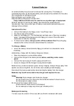
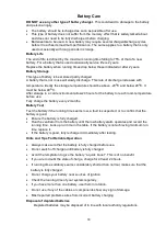
Page 27: ...rve power unless an external battery is connected The ventilator will select its power source according to the power available in the following sequence 1 Mains Electricity 2 External Battery if connected 3 Internal Battery if fitted In order to save battery power the ventilator will always run on mains electricity if it is present If the mains fails or is not connected the ventilator will select ...

Page 28: ...m 20BPM IPAP Run Time Hours Min Run Time Hours 15 11 8 25 20 9 5 7 25 25 8 5 6 25 30 6 5 5 35 5 5 4 38 5 3 75 Low Battery Alarm When the battery is almost depleted the battery icon will flash and change colour to red When the battery is depleted an alarm will sound accompanied by an on screen message Battery Power Running Low When battery power reaches a critical level the alarm will change to a c...

Page 29: ...ry Life The end of life is defined by the maximum running time falling to 75 of that of a new battery For a battery that is used occasionally service life is 2 years Replace the battery when running times drop below those indicated or after 2 years Internal Battery Replacement The internal battery should be replaced every 2 years or after 10000 hours use or if the run times are shorter than expect...

Page 30: ...n the connector and withdraw the connector To Charge a Battery Leave the battery connected to the Nippy jnr whilst it is connected to mains electricity Alternatively charge with the battery charger as follows Place the charger on a smooth flat surface Connect the charger to the battery socket before switching on the mains power Connect the mains plug to the AC supply and switch on Leave on charge ...

Page 31: ...r the battery to reach room temperature before use Fully charge the battery every 2 months Battery Test Test the battery if the running time seems low a fault is suspected or to confirm that the battery is good Ensure the battery is fully charged Run the ventilator from the battery until the low battery alarm operates and record the running time Look up run time in the table If the battery is not ...

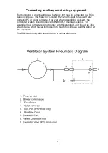
Page 32: ...for use with any domestic PC or laptop computer However when assembling a system the completed system should comply with EN60601 1 medical systems For example most computers do not comply with this standard so it should be sited at a distance which makes it impossible to touch the computer and the patient at the same time The RS232 port may also be used to run a remote alarm unit ...

Page 33: ...p Rate 6 60 Breaths per minute Type of protection against electric shock Class 1 equipment Degree of protection against electric shock Type B to EN 60601 1 Mode of operation Continuous IP rating X0 Storage environment 20 to 50 O C 5 85 RH 260 1100 mBar atmospheric pressure Internal battery 24Vdc 6 8 Ahr Running time 4 12 hours depending on settings and leak External battery 24Vdc 6 8 Ahr Running t...

Page 34: ...lly switch to the back up supply and give an audible and visual indication that it has done so During total power failure there will be no output from the machine The patient will be able to breathe spontaneously through the machine and out through the exhale port However some re breathing of exhaled gas is inevitable During power ventilator failure disconnect the patient from the breathing circui...

Page 35: ...ilator in direct sunlight Avoid places where there is excessive humidity or dust which may cause damage to internal parts Keep the Nippy jnr away from extreme direct heat such as fires heating radiators etc and always allow a 100mm 4 0in air space around the unit when in use If liquids are allowed to enter the unit serious damage could occur If you spill any liquid into the Nippy jnr consult quali...

Page 36: ...with water Input Air Filter The input air filter should be inspected weekly It is located on the rear of the machine To remove the filter grip the filter housing with the thumb and forefinger across the top corners and pull the filter cover away from the ventilator Remove and inspect the element To clean the filter element wash gently in tepid soapy water Rinse and allow the element to dry When th...

Page 37: ...ing is the customer s responsibility Use the original packing materials whenever possible In the event of a breakdown or damage to the ventilator refer servicing or repair to qualified and competent technical personnel Factory Service Repair B D Electromedical products returned for factory service or repair must have a Return Material Authorisation RMA number assigned This is essential for efficie...

Page 38: ...justment but allows the user to switch the ventilator on and off Total lock The ventilator can be locked to prevent unauthorised adjustment or power off To lock press and and SET buttons simultaneously and hold for 2 seconds To unlock press and and SET buttons simultaneously and hold for 2 seconds In this mode the ventilator must be unlocked before it can be switched off This page may be removed b...

Reviews: