SERIES 762 BIDIRECTIONAL SLURRY KNIFE GATE VALVES
Installation, Operation, and Maintenance Manual
24 of 30
© 2021 BRAY INTERNATIONAL, INC. ALL RIGHTS RESERVED. BRAY.COM The Information
contained herein shall not be copied, transferred, conveyed, or displayed in any manner that would
violate its proprietary nature without the express written permission of Bray International, Inc.
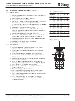
Seat
Retainer
Retainer bolts/nuts
14.2
SEAT REPLACEMENT
14.2.1 1. Relieve the line pressure and close the valve. Flush the line if
necessary.
2. Retract the gate to full open condition.
3. Remove the valve from the line.
4. Clamp the valve in the vertical position (up to 12”/300mm) and
in the horizontal position (for the sizes above 12”/300mm) to a
fixture. Do not block the valve port when clamping the valve. An
overhead hoist may be needed for larger size valves.
5. Verify that the valve bore is clear of all debris, scale, and
elastomer residue.
6. Remove the retainer flange bolts taking caution to prevent
retainer flanges from falling free. Remove the retainer flanges
from the valve.
7. Remove the seats from the valve by gently pulling them out.
8. Lay the valve down in a horizontal position on a flat surface.
9. Check the bore diameter for unusual or excessive wear. If found,
valve housing may require replacement.
10. Lubricate the O.D. and sealing lip of the first seat. Use
recommended lubricant.
11. Install the seat, being careful to center the flange end in the
bore of the housing.
12. Place a retainer flange on the top of the seat. Align the retainer
flange bolt holes with the matching holes in the round flange.
Align the I.D. of the seat and retainer flange.
13. Install the retainer bolts. Only tighten sufficiently to allow
installation of the next bolt. Continue this until all bolts are
installed.
14. Once all bolts are in place, tighten the retainer flange bolts using
a cross pattern until there is a 0” - ⅛” (0 - 3 mm) gap between
the retainer flange and the housing. Do not cycle valve with only
one seat in place.
15. Turn the valve over so the installed seat is on the flat surface.
16. Lubricate the O.D. and sealing lip of the second seat. Use
recommended lubricant.
17. Install the second seat and retainer flange in a similar way.
18. The valve is now ready for installation. The gate must remain
in the open position until the valve is installed and ready for
operation.
(continued)
Figure 6:
Seat replacement
assembly


