


3DJH
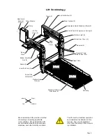
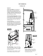
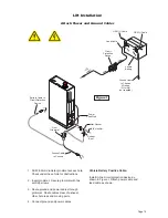
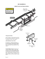
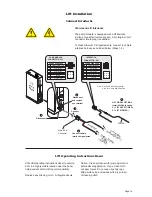
Lift Installation
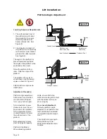
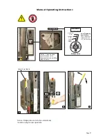
Tower Microswitch Adjustment
Tower 1 (Unfold) Switch Adjustment
Floor Position from Stow
1. Position platform at the fully stowed
position using the manual hand pump or
pendant control.
2. Turn switch adjustment screw clockwise 3
full turns.
3. Press pendant UNFOLD switch (continue
pressing switch until platform stops unfold-
ing).
4. When platform stops unfolding, turn switch
adjustment screw counterclockwise while
pressing the pendant UNFOLD switch.
Platform position will change. Repeat ad-
justment until criteria below is met.
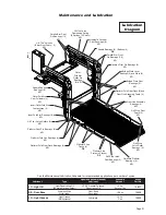
Proper Adjustment Criteria:
%ULGJHSODWHVKRXOGMXVWUHVWRQEDVHSODWH
cover. See Photo C.
6KRXOGEHDQDSSUR[LPDWHPPFOHDU
-
ance between outboard end of rotating
pivot slide arm saddle and the lower
parallel arm. See Photo B.
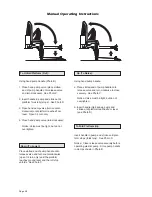
Tower 2 (Up) Switch Adjustment
Floor Position from Below Floor
1. Lower platform a minimum of 15.25 cm
EHORZÁRRUOHYHOSRVLWLRQXVLQJWKHPDQXDO
hand pump or pendant control.
2. Turn switch adjustment screw counter-
clockwise 3 full turns.
3. Press pendant UP switch (continue press-
ing switch until platform stops).
4. When platform stops, turn switch adjust-
ment screw clockwise while pressing the
pendant UP switch. Platform position will
change. Adjust platform to meet criteria
listed for Tower 1 Switch "Proper Adjust-
ment Criteria".
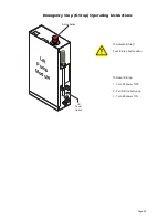
TOWER
2
TOWER
1
32942
TOWER
4
TOWER
3
32943
Figure D
TOWER
2
TOWER
1
32942
TOWER
4
TOWER
3
32943
Review adjustment
procedures below and
adjust as needed only.
Left (rear) pump lift depicted.
Right (front) pump lift is a
mirrored image.
C
Bridge plate should rest on base plate cover.
3 mm
B
36514
Summary of Contents for Century 2 CLXT
Page 42: ...Page 40...


