


Page 16
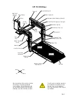
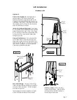
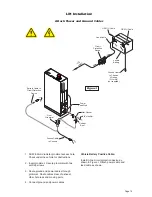
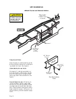
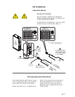
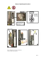
Lift Installation
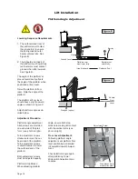
Platform Angle Adjustment
Adjustment Screw
A
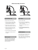
Lowering Sequence Requirements
1. The outboard end (toe) of
the platform must contact
WKHJURXQGÀUVWWRHQVXUH
the spring-loaded outer
barrier
unfolds fully. See
Figure B.
2. The inboard end (heel) of
the platform must lower fully
(vertical arms must contact
ground when fully lowered).
See Figure B.
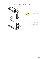
The angle of the platform at
ground level directly affects
the angle of the platform when
SRVLWLRQHGDWÁRRUOHYHO
5DLVHWKHSODWIRUPWRÁRRU
level. Note the angle of the
platform.
7KHSODWIRUPDWÁRRUOHYHO
should have a slight upward
angle as shown in Figure C.
Adjust platform angle as de-
tailed below.
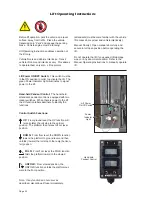
Adjustment Procedure:
Platform angle adjustment
Allen screws are provided
on each side of the plat-
form (see photo at right).
Turn adjustment screws
clockwise to raise the out-
board end
of the platform.
Turn adjustment screws
counterclockwise to lower
the outboard end
of the
platform.
Both adjustment screws
must be adjusted equally.
Platform Stop Blocks:
When adjusting platform
angle, ensure both stop
blocks are making full contact
with the vertical arms (see
photo at right).
Floor Level Adjustment:
Following platform angle
DGMXVWPHQWVHWSODWIRUPÁRRU
level positioning as detailed
in Tower Microswitch Adjust-
ment.
Check platform angle again
after performing Tower
Microswitch Adjustment pro-
cedures.
Figure B
Vehicle
Floor
Level
Wedges (option)
Figure C
(Heel) Inboard
Outboard (Toe)
Heel
Ground Level
Barrier must
unfold
fully.
Platform heel
must lower
fully.
Barrier
2
1
Stop
Block
Vertical
Arm
Stop blocks must
make full contact.
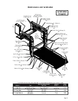
36514
Summary of Contents for Century 2 CLXT
Page 42: ...Page 40...


