background image

13

User Manual

Maintenance

7.1 

Removing the Blades for Cleaning and Replacement

!

Warning!

Disconnect the printer from the electrical outlet.

!

Caution!

Risk of injury.  The cutter blades are sharp.

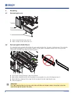
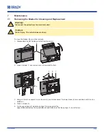
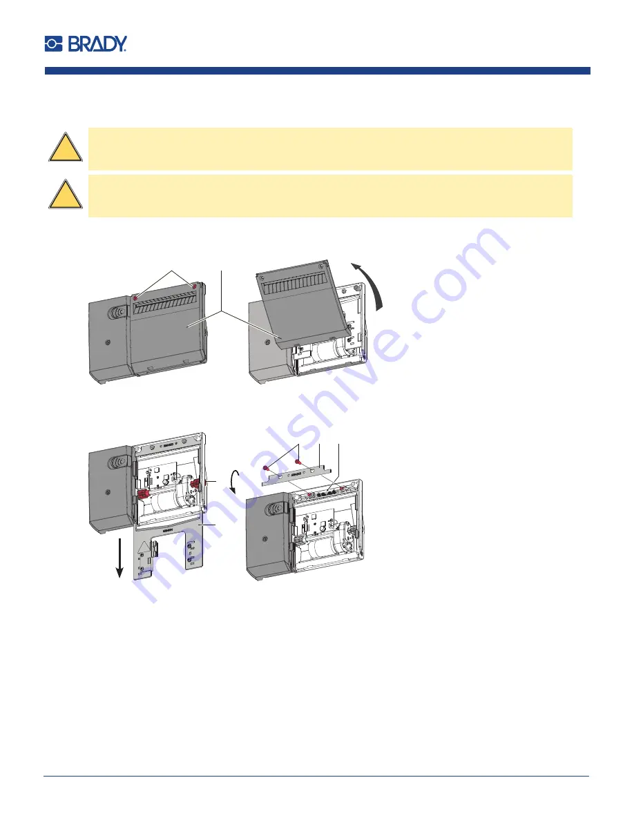
To clean the blades, they must be removed. 

1. 

Disassemble the NG Guillotine Cutter from the printer.

1

2

2. 

Loosen screws (1) and remove cover (2) towards the front.

6

5

7

3

4

3. 

Using a 2.5mm hex wrench to turn the axle (3) counterclockwise. The lower blade (4) is moved down until it can be 

pulled out.

4. 

Loosen screws (5). 

5. 

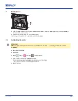
Fix the upper blade (6) while the springs (7) press against the 


upper blade (6).Remove the upper blade (6) and make sure that the springs (7) do not fall out.

Summary of Contents for NG Guillotine Cutter Heavy Duty

Page 1: ...USER MANUAL NG Guillotine Cutter Standard and Heavy Duty ...

Page 2: ...tions 7 3 4 Environment 7 3 5 Technical Data 7 4 Mounting 8 4 1 Removing Covers 8 4 2 Removing Anti Static Brush 8 4 3 Mounting Cutter 9 4 4 Mounting Cutter Tray 9 5 Operation 10 5 1 Preparation 10 5 2 Standard Operation 11 5 3 Cutting on Demand 11 6 Printer Configuration 12 7 Maintenance 13 7 1 Removing the Blades for Cleaning and Replacement 13 7 2 Lubricating the Blades 14 7 3 Reassembling the ...

Page 3: ...eferenced in this manual are trademarks or registered trademarks of their respective companies or organizations 2020 Brady Corporation All rights reserved Editor Regarding questions or comments please contact Brady Technical Support Topicality Due to the constant further development of products discrepancies between documentation and product can occur Please check BradyID com for the latest update...

Page 4: ...s Operation of this equipment in a residential area is likely to cause harmful interference in which case the user may be required to correct the interference at his own expense Changes or modifications not expressly approved by the party responsible for compliance could void the user s authority to operate the equipment This device complies with Part 15 of the FCC Rules Operation is subject to th...

Page 5: ...rvices Asia Pacific brady co uk landing pages global landing page Australia bradyid com au en au supportlanding Canada bradycanada ca Latin America bradylatinamerica com Registration Information To register your printer go to bradycorp com register Repair and Return If for any reason you need to return the product for repair please contact Brady Technical Support for repair and replacement informa...

Page 6: ... display 3 2 Intended Use The device is intended exclusively as an option for the i7100 printer in the basic version for cutting suitable materials Any other use or use going beyond this shall be regarded as improper use The manufacturer supplier shall not be liable for damage resulting from unauthorized use the user shall bear the risk alone Usage for the intended purpose also includes complying ...

Page 7: ... X Do not open the device casing 3 4 Environment Obsolete devices contain valuable recyclable materials that should be sent for recycling X Send to suitable collection points separately from residual waste The modular construction of the device enables it to be easily disassembled into its component parts X Send the parts for recycling X Take the electronic circuit boards to public waste disposal ...

Page 8: ...mpatible with the cutter This may require replacing the anti static brush that came with the product 2 1 3 4 5 6 X Turn lever 6 counterclockwise to open the printhead X Remove the anti static brush 5 from the printer by removing the screw 4 via the threaded hole 1 X Ensure that the embossing 3 un snaps from its counterpart 2 when loosening the screw X Close the printhead Attention For cutter opera...

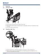
Page 9: ...utter will be connected to the peripheral port 2 of the printer X Secure the cutter 5 with the screw 4 4 4 Mounting Cutter Tray 4 2 1 3 1 X Hook the cutter tray box 3 with the fixing brackets into the recesses 1 on the mounted cutter 2 X Slide the divider 4 according to the label height into the corresponding groove in the cutter tray box This ensures a correct stacking of the cut labels ...

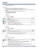
Page 10: ...ead and the drive roller so that the front edge of the strip reaches through the cutter X Insert ribbon Instructions of the printer X Fold up and lock the cutter unit 2 X Activate the cut mode in the software In direct programming use the C command Programming Manual of the printer X Configure the cut parameters 6 Printer Configuration i Note The cut parameters are only accessible with cutter inst...

Page 11: ... be cut as chosen in the software after each label after a specific quantity of labels or at the end of a print job i Note Between the print jobs a direct cut can be released by pressing on the control panel i Note In case the material do adhere in follow of electrostatic charge it s possible to mount an antistatic brush Part No 170345 on the printer 5 3 Cutting on Demand In the Cut on Demand mode...

Page 12: ...ngs of configuration and software are added together 0 0 mm Label Sensor X Start menu X Select Setup Labels Parameter Meaning Default Label sensor Method for detecting the starting end of the label Gap Sensor Detection using changes in the transparency between the label and label gap Bottom Reflect Detection using reflex marks on the bottom of the medium Continuous media Checking the existence of ...

Page 13: ...e removed 1 Disassemble the NG Guillotine Cutter from the printer 1 2 2 Loosen screws 1 and remove cover 2 towards the front 6 5 7 3 4 3 Using a 2 5mm hex wrench to turn the axle 3 counterclockwise The lower blade 4 is moved down until it can be pulled out 4 Loosen screws 5 5 Fix the upper blade 6 while the springs 7 press against the upper blade 6 Remove the upper blade 6 and make sure that the s...

Page 14: ...des grease must be applied Attention Use only a plastic grease to grease the blades and running surfaces Grease sliding surfaces Grease guide slots 7 3 Reassembling the Blades The assembly of the cleaned or new blades and the assembly of the cutter is carried out in the reverse order of disassembly 2 1 3 4 5 X Put on the upper blade 2 and make sure that the springs 3 should not be kinked and remai...

Page 15: ...e automatically aligns 7 4 Calibrating the cutter Attention After every blade change and removal and installation of the blades for cleaning the blades must be calibrated X Remove label material X Start menu X Select Setup Cutting Calibrate device X Press Continue to start the calibration process After a cutter movement the display shows Device successfully calibrated If the calibration failed an ...

Page 16: ...nted X Mount the cover Device not locked Cutter is not in operating position Tear off Plate not mounted X Fold up and lock the cutter unit X Mount the Tear off Plate Device too hot Temperature of the cutter is not in the allowed range X Let cool down the cutter Media too thick The media cannot be cut but the blades can return in the home position X Press Cancel X Change material Warning message Ca...

Page 17: ...17 User Manual This page intentionally left blank ...

Page 18: ...art No 151153 Brady Worldwide Inc 6555 West Good Hope Road Milwaukee WI 53223 bradyid com Brady EMEA Lindestraat 20 9240 Zele Belgium bradycorp com global Brady Corporation Asia 1 Kaki Bukit Crescent Singapore 416236 bradycorp com global ...

Reviews: