Express
®
Crescent
®
Lavatory System - CRS-Series
Installation Instructions
CRS-2/IR, CRS-3/IR
7
Bradley Corporation • 215-1330 Rev. K; EN 06-915
2/8/07
Installation Instructions continued . . .
Step 8:
Electrical and supply connections
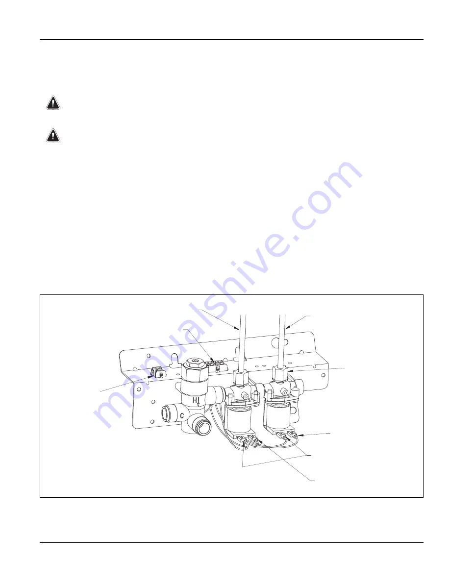
NOTE: Refer to Figure 6a below for CRS-2/IR or Figure 6b on page 8 for CRS-3/IR.
WARNING:
The Adaptive® Infrared control must be connected with a 24 VAC
Class II transformer. Connections to 110 VAC will result in damage to
the electronics and can cause personal injury.
CAUTION:
Connection of leads other than shown may cause permanent damage
to the sensor.
NOTE: Compliance and conformity to local codes and ordinance is the responsibility of the installer.
NOTE: The solenoid valves have been pre-wired.
1. Snap the senser circuit plug from the bowl into the solenoid circuit plug located on the valve bracket.
2. Snap the transformer circuit plug into the female transformer circuit plug located on the valve bracket.
3. Turn on the water supply to the Express® Crescent® Lavatory System and check for leaks.
4. Plug in the transformer and wait at least two minutes to allow the sensor to adapt to the environment.
5. Pass your hand in front of each station’s sensor until all the air is purged from the lines and water
is flowing smoothly.
NOTE: The Vernatherm mixing valve is NOT factory preset. Upon installation, the temperature of this
valve must be checked and adjusted to ensure delivery of a safe water temperature. Water in excess of
110°F (43°C) may cause scalding.
GREEN
S
UPPLY TUBE
(FROM
S
PRAYHEAD)
RED
S
UPPLY TUBE
(FROM
S
PRAYHEAD)
RED
S
PADE TERMINAL
GREEN
S
PADE TERMINAL
S
EN
S
OR CIRCUIT PLUG
COMPRE
SS
ION NUT
(110-231)
TRAN
S
FORMER
CIRCUIT PLUG
WHITE
S
PADE TERMINAL
Figure 6a


