background image

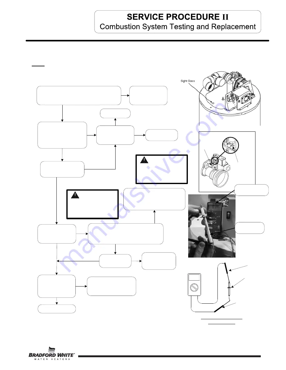
D

oes


in

l

et


gas


pressure


drop


more


than


2

"


W

.

C

during


burner


ignition

?

A

d

j

ust


gas

supp

l

y


regu

l

ator

I

nade

q

uate

l

y


si

z

ed


regu

l

ator

.

Y

N

N

Y

N

Y

N

V

erify


M

inimum


G

as


Supp

l

y


Piping


Re

q

uirements


of

:


M

inimum


¾"

 N

P

T

(Schedu

l

e


4

0


b

l

ac

k

 I

ron


Pipe


recommended)

.

Reconfigure


gas


supp

l

y


piping

Y

O

bser

v

e


burner


operation


through


the


sight


glass


located


on


the


combustion


insert


mounting


flange.


N

ormal


burner


operation


should


ignite


smoothl

y

,


without


e

v

idence


of


coughing


or


huffing


upon


ignition.


T

he


burner


flame


should


be


a


blue


flame


near


the


burner


surface


in


a


uniform


flame


pattern.

 O

ccasional


y

ellow


or


white


strea

k

s


are


normal.


I

nlet


gas

pressure


tap

V

enturi

ad

j

ustment

D

oes


main


burner


L

ight

?

Remove


high


vo

l

tage


wire


connected


at


the


spar

k


rod


and


ho

l

d


appro

x

imate

l

y


¼"


from


meta

ground


with


insu

l

ated


p

l

iers


during


the


ignition


cyc

l

e


(3


second


spar

k


tria

period)

.

I

s


there


spar

k


to


ground

?

Y

N

Chec

k


spar

k


gap


to


burner

(see


“Spar

k


Rod


G

ap


I

nspection”)

Chec

k


resistance


of


high


vo

l

tage


cab

l

e

Resistance


shou

l

d


be


0

-

1


ohms

I

f


resistance


is


high,


rep

l

ace


spar

k


cab

l

e

. I

f


spar

k


cab

l

e


is


good,


rep

l

ace


Contro

B

oard

.

N

Y

Can


Spar

k

ing


be


seen

/

heard


at


the


spar

k


rod


to


the


burner

?

Proceed


to


ne

x

t


page

W

ith


manometer,


chec

k


in

l

et


gas


pressure

. I

s


it


stab

l

e


between


7

"


&


1

4"


W

.

C

static

?

(heater


not


running)

(see


i

ll

ustrations


at


right)

I

s


gas


supp

l

y


pressure


regu

l

ator


ad

j

ustab

l

e


to

maintain


proper


and


stab

l

e


setting

Y

N

W

A

R

NIN

G

120


vo

l

t


potentia

exposure

Use


caution

making


vo

l

tage


checks


to


avoid


persona

injury

.

W

A

R

NIN

G

Removing


screw


from


in

l

et


gas


pressure


tap


wi

ll 

immediate

l

y


a

ll

ow


gas


to


f

l

ow


from


pressure


tap

N

ote: Mode

l

s


using


meta

fiber


mesh


burner


a


red


g

l

ow


from


the


burner


surface


is


norma

l.

3

1

Chec

k


continuity


of


spar

k


rod

. I

s


reading


0

-

1


Ohm

?

Y

N

Rep

l

ace


Spar

k


Rod

(see


“Spar

k


Rod


G

ap

 I

nspection


and


Rep

l

acement”

C

HE

C

S

P

A

R

RO

D


R

E

S

I

S

T

A

N

C

E

M

eter


probe

M

eter


probe

S

par

k


R

od

V

olt


meter


set


to

O

HM


setting

V

oltmeter


set


to


O

HM


setting

S

par

k


R

od

31

Summary of Contents for U100L199E N Series

Page 1: ...ng Guide and Instructions for Service To be performed ONLY by qualified service providers Models Covered by This Manual U65L155E N A U65L199E N A U65L270E N A U100L199E N A U100L270E N A U100L300E N A...

Page 2: ...Tube Inspection Replacement 35 III Gas Valve Replacement 37 IV Blower Testing and Replacement 38 V Flame Sensor Testing and Replacement 40 VI Spark Rod Replacement 42 VII Ignition Module Control Board...

Page 3: ...ignition flame sensing and lockout The module will also provide diagnostic information to help in determining the cause of system lockouts The contents in this manual are detailed informational tools...

Page 4: ...res for a given component Contact Technical support immediately if diagnosis is not determined using the methods described in this service manual Manometer Two types available a liquid U tube type or...

Page 5: ...ced number of parts for servicing and wiring Plug in wiring reduces chance of miswirng Burner ignition with direct spark ignition A high voltage spark jumps from the spark rod to the burner surface to...

Page 6: ...n Dia in Relief Valve in Model Number Capacity GAL Input BTU Hr NAT U65L155E3N A 65 155 000 203 56 6 10 37 39 61 58 1 U65L199E3N A 65 199 999 249 56 6 10 37 39 61 58 1 U65L270E3N A 65 270 000 320 56 6...

Page 7: ...AC primary 24VAC secondary 40VA Blocked Vent Safety Switch Normally closed opens 240 F manual reset Blower 120VAC 60Hz 6 1 amps 6400 RPM Approved Gas Type Natural gas only Gas supply must match the ga...

Page 8: ...h contacts normally closed or circulator flow switch and damper contacts normally open remain open after being energized then the ignition sequence will not start and an error code 29 Safety switch ci...

Page 9: ...r resetting this error code 3 ERROR CODE 62 or 63 Control board will go into Soft Lockout if the main burner cannot be lit or fails to prove flame after 3 ignition trials The water heater display indi...

Page 10: ...present between RED and BLACK wire pin connections on the back of Control Display 1 2 3 8 6 5 4 3 1 1 2 1 4 1 3 3 2 1 1 5 3 P2 P4 P5 P7 P3 CONTROL BOARD P10 P9 J1 Refer to Control Board illustration V...

Page 11: ...mperature sensors Error code 63 on display see Combustion System Testing and Replacement Does blower post purge for 30 seconds System okay N Y N N N Y Y Y Y From previous page N CAUTION Use caution no...

Page 12: ...Up buttons together and hold for 3 seconds until Max Setpoint is shown in the display Step 2 Pressing Select button will change display to next mode SELECT SET Status F idle Operational Water Temp The...

Page 13: ...sor Temperature Displayed Water Temperature Average SELECT SET Status F idle Water Temp Operational 13 SELECT SET Status F idle Operational Max Setpoint value in Water Heater Display Max Setpoint 3 Fl...

Page 14: ...d Control 4 Setpoint Display Change SELECT SET Status F idle setpoint Operational 5 F C Display Change SELECT SET Status F C idle Operational F setpoint 6 Differential Display only shows the different...

Page 15: ...mperature setpoint Step 1 In service mode press the Select button until Max Setpoint is displayed WARNING Setting the water temperature to the maximum set point can result in scalding hot water delive...

Page 16: ...lue This will limit the maximum setpoint the user can select Note The maximum setpoint is approximately 180 F Step 4 Press Set button to confirm new Max Setpoint value and stop setting mode Max Setpoi...

Page 17: ...maximum setting The Water Heater Display can be set back to the User Mode immediately by pressing both the Temperature Up and Select buttons together for 3 seconds SELECT SET Status idle Operational M...

Page 18: ...ugh hot water to start the burners Step 2 Enter the Service Mode described previously Step 3 Press the Select button until a number value is displayed with Flame Current to the right of the number The...

Page 19: ...lay WARNING Setting the water temperature to the maximum set point can result in scalding hot water delivered to the faucets It is highly recommended that the maximum setpoint be adjusted to the lowes...

Page 20: ...ECT SET Status F idle setpoint Operational To Display and Change Temperature Format F C To Change Temperature Format in Display from F to C or C to F Step 1 While in Service Mode press Select button u...

Page 21: ...button to change temperature format to C SELECT SET Status idle Operational C F C Step 3b Press Temperature Down button to change temperature format to F SELECT SET Status idle Operational F F C Step...

Page 22: ...Water Heater Display and the following section in this Service Manual explains the error codes with corrective actions to repair the water heater SELECT SET idle Service Needed Example of Error Code...

Page 23: ...p 2 Press the Temperature Down button to select the error code index starting with the most recent error code 10 SELECT SET Status idle Operational Step 3 Press the Select button to view the error cod...

Page 24: ...next error code index and press Select to view the error code number if any for that index number Continue on to index 1 the oldest error code index The water heater display will store up to 10 error...

Page 25: ...ORMAL SEQUENCE BEFORE OPENING GAS VALVE OR AFTER CLOSING GAS VALVE FLAME DETECTED BEFORE IGNITION FLAME DETECTED AFTER A HEATING CYCLE COMPLETES LOWER SENSOR READINGS FAULTY FLAME ROD SHORTED TO GROUN...

Page 26: ...portion of the display The control will also go through 3 attempts to relight the burners every hour in the soft lockout condition All other error codes will put the water heater into a Hard Lockout c...

Page 27: ...ice Mode Turn power OFF Draw water to cool tank below 120 F Check sensor Sensor is held in place with a clip fastened to the well see photo Check sensor wire for potential damage or breaks in the wire...

Page 28: ...h on power to the water heater Enter service mode on the water heater display see illustration Press button under Lockout Reset and hold for 3 seconds Set thermostat to the desired setting Water heate...

Page 29: ...3 2004 1966 1928 1891 1856 1820 1786 1753 1720 160 1688 1656 1625 1595 1566 1537 1509 1481 1454 1427 170 1402 1376 1351 1327 1303 1280 1257 1235 1213 1191 180 1170 1150 1129 1110 1090 1071 1053 1035 1...

Page 30: ...d reinstall senor clip Step 7 Reconnect the sensor connector to the control board and route the wire harness through the same path that it was removed Step 8 Restore 120 volt power supply Confirm prop...

Page 31: ...to ground Y N Check spark gap to burner see Spark Rod Gap Inspection Check resistance of high voltage cable Resistance should be 0 1 ohms If resistance is high replace spark cable If spark cable is g...

Page 32: ...ss located on the combustion insert mounting flange Normal burner operation should ignite smoothly without evidence of coughing or huffing upon ignition The burner flame should be a blue flame near th...

Page 33: ...all control panel and all the wire harnesses attached to it Step 9 Remove the two pieces of insulation that cover access to the burner mounting insert Step 10 Remove the 4 nuts 7 16 socket holding the...

Page 34: ...4 Re install the jacket head and components that were removed in step 8 from the previous page Step 5 Reconnect wire harnesses to the flame sensor spark rod connection blower damper circulator flow sw...

Page 35: ...er access to the burner mounting insert Step 10 Remove the 4 screws philips head that hold the Spark Rod and Flame Sensor Step 11 Remove the Spark Rod and Flame Sensor The gaskets will need to be repl...

Page 36: ...tep 12 on previous page Tighten the nuts evenly Step 4 Carefully reinstall flame sensor with gasket and direct spark igniter DSI with gasket and secure with screws from step 11 on previous page Step 5...

Page 37: ...nge Step 8 Install new gas valve with new gasket provided Secure gas valve in place using screws from step 6 Step 9 Reconnect PVC damper assembly gas supply wire harness and silicone tubing to gas val...

Page 38: ...nd black wires at location P3 on the control board see photo at bottom N N Refer to ignition module control board illustration Is there 120VAC between P7 5 and P7 3 Y Replace ignition module control b...

Page 39: ...for gas leaks repair any gas leaks found Step 13 Reconnect wire harnesses to blower assembly and gas valve restore 120 volt power supply to water heater and confirm proper operation following the ligh...

Page 40: ...should maintain beyond the 1 5 second flame proving period Is there 24VAC between P5 5 and P5 8 Y N Call for technical support Replace flame sensor with gasket and or wire lead see Flame Sensor Repla...

Page 41: ...n contact with burner flange Step 8 Install new flame sensor with new gasket provided using screws from step 6 Arrange flame sensor with hook towards burner Step 1 Position main power switch to OFF St...

Page 42: ...ounting hole only allow installation one way Check distance between spark rod and blower transition tube shown below Step 1 Position main power switch to OFF Step 2 Disconnect unplug water heater from...

Page 43: ...of the slots on the control panel and remove control Step 9 Replace control board and all wire connections Step 10 Re attach the display panel from step 5 using the same screws Step 11 Restore 120 vo...

Page 44: ...he 2 screws short Phillips screw driver holding the transformer in place and remove transformer from control panel see photo right Step 6 Install new transformer and secure in place with screws from s...

Page 45: ...cement apply thread sealing tape or other thread compound to threads of anode and reinstall into heater Restore water supply and check for and repair any leaks found Step 7 Restore 120 volts to water...

Page 46: ...120 volt power source Step 7 Turn off water supply and drain water heater Step 8 Once the water heater is drained remove the cable ties holding on the pipe insulation Save the pipe insulation to repl...

Page 47: ...ge vent termination Contact your plumbing professional to correct this issue Step 4 When no blockage or downdraft issues are present check the continuity of the switch see photo below If there is no c...

Page 48: ...between black and white wires There should also be 102 to 132 volts between blue and white wires when there is a call for heat Step 5 If 120 volts is not present from either two inspection points che...

Page 49: ...r Gas Line Static Manifold Running Inlet Gas Pressure Spark Rod Resistance Flame Sense Micro Amps Venturi Setting from Bottom in Turns Combustion CO2 CO Installation Site Contact Name Phone Number Ser...

Page 50: ...per Bracket Specify Model 9 Thermostat Sensor 10 Utility Cover 11 Circulator Assembly 12 NPT Nipple 13 Stainless Flex Connector 14 NPT SAE Adapter 15 T P Specify Model 16 Hot Water Outlet Plastisert N...

Page 51: ...ify Model 4 Blower Specify model 17 Burner Specify Model 5 Damper Assembly Specify Model 18 Burner Mount Assembly 6 Transition Tube 19 Sight Glass Assembly 7 Gasket Blower Transition 20 Gasket Sight G...

Page 52: ...ed Vent Switch Harness 24V 4 Display Panel 14 T Stat Harness 24V 5 Screw 15 Control Display Harness 24V 6 Switch Main Power 16 Blower Harness 120V 7 Control Display 17 Circ Flow Harness 120V 8 Screw 1...

Page 53: ...Cut Off GFI Ground fault interrupt GPM Gallons per Minute HSI Hot Surface Igniter Hz Hertz LED Light Emitting Diode NOx Oxides of Nitrogen NPT National Pipe Thread PSI Pounds per Square Inch RPM Revo...

Page 54: ...NOTES 54 54...

Page 55: ...NOTES 55 55...

Page 56: ......

Reviews: