background image

Condensing PDV Series


40 


Service Procedure XIV 

Condensate Trap Removal, 

Inspection, & Replacement   

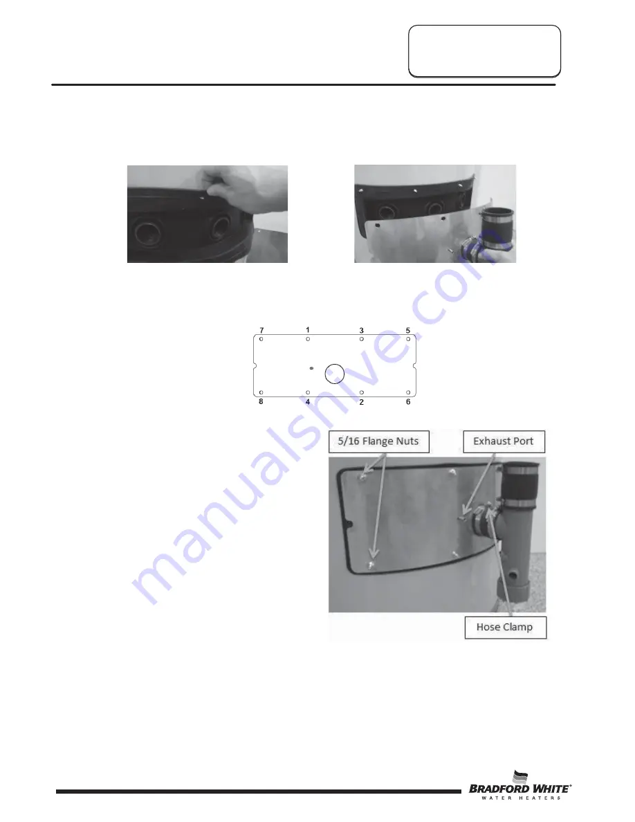
d.  Align the gasket flange holes to go over the studs extending through the jacket.  After 

verifying that the studs are through the flange holes and that the gasket is sealed 

around the secondary flue tubes, return the cover such that the studs extend through 

the openings. 


e.  Hand start the nuts that were removed in step 3 onto the studs on all 8 locations to 

ensure a proper fit.  Begin securing the 5/16” nuts with an wrench or a socket.  This 

process should be done following the diagram below.  Each flange nut should be 

tightened to 25 in*lbs. 


Step 6.  Once all the flange nuts are back in place, 

reconnect the ¼” clear tubing onto the port 

on the cover. 

Step 7.  Connect the condensate tee and coupler to 

the neck provided on the cover and secure 

by tightening the hose clamp. 


Service Procedure XV 

Exhaust Collector Removal, 

Inspection, & Replacement   

40

Summary of Contents for LC2PDV50H76

Page 1: ...1 19 SERVICE MANUAL Troubleshooting Guide and Instructions for Service To be performed ONLY by qualified service providers Models Covered by This Manual RC2PDV50H N X LC2PDV50H76 N X Denotes Warranty...

Page 2: ...ent 17 II Pressure Switch Testing Replacement 18 III Blower Testing Replacement 20 IV Blower Temperature Switch Testing Replacement 22 V Gas Control Testing Replacement 24 VI Simulated Resistive Devic...

Page 3: ...one Gas detectors are available Contact your gas supplier or plumbing professional for more information CAUTION Turn OFF or disconnect the electrical power supply to the water heater before servicing...

Page 4: ...ases blower life by reducing bearing wear and noise Rugged Wiring Connections receptacle type connections promote error free wiring Increased Vent Lengths increased venting performance is achieved whi...

Page 5: ...ls Required for Service Manometer A liquid U tube type or a digital magnahelic type can be used This device is used to measure gas and or air pressure and vacuum Multi Meter A digital type is strongly...

Page 6: ...al 188 F 87 C Commercial 199 F 93 C Residential Temperature Set Point Range 60 F 16 C to 160 F 71 C approximate temperatures Commercial Temperature Set Point Range 80 F 27 C to 180 F 82 C approximate...

Page 7: ...10 3 1 Through the Wall 2 110 33 5 10 3 1 Through the Wall 3 105 32 0 10 3 1 Through the Wall 4 100 30 5 10 3 1 Through the Wall 5 95 29 0 10 3 1 Through the Roof 0 120 36 6 15 4 6 Through the Roof 1...

Page 8: ...d maximum 1 second minimum Post purge 15 Seconds PS Fault Delay failed open close Retry after 2 minutes Soft Lockout Retry after 5 minutes ECO Limit Lockout Indefinite see PV SERVICE PROCEDURE VI page...

Page 9: ...with a 3 second pause The gas control waits 2 minutes and then the blower runs for 30 seconds This cycle repeats until the safety circuit opens 2 Blower energizes 3 Pressure Switch Proves Blower Vent...

Page 10: ...9 Burner off 10 Blower post purges 15 seconds Abnormal Operation 1 Simulated Resistive Device Fault a If the resistance is greater than 70 000 ohms The gas control immediately turns off all outputs T...

Page 11: ...turns off and the control flashes 3 times with a 3 second pause The gas control waits 2 minutes before turning on the blower for another 30 seconds to check if the circuit will close This cycle repea...

Page 12: ...tion begins If the recycle count limit has been reached the gas control turns off the blower and flashes 6 times then 3 times with a 3 second pause The gas control waits 5 minutes before repeating the...

Page 13: ...locked or restricted 3 Oxidation build up on pilot electrode 4 Wire damage to pilot assembly or bad connection at gas valve 5 Low gas pressure Page 17 Procedure II Two flash three second pause Pressur...

Page 14: ...ed 3 Oxidation build up on pilot electrode 4 Wire damage to pilot assembly or bad connection at gas valve 5 Insufficient combustion air 6 Gas pressure is out of specification 1 4 Page 17 5 Refer to in...

Page 15: ...lot flame should be stable Some causes for an unstable pilot flame are a The water heater vent is less than the allowable vent length b The gas pressure is out of specification c The pilot flame is no...

Page 16: ...e the burner assembly from the combustion chamber Step 7 Thoroughly inspect the burner surface area and burner port area and remove any loose debris Step 8 Unscrew the burner from the main burner orif...

Page 17: ...there is no continuity Step 10 Visually inspect the igniter flame sense electrode for deterioration Replace the pilot as necessary The electrode should not be in contact with the pilot hood If so car...

Page 18: ...Y N Y Check tubing and pressure tap on switch for blockage Is there blockage Check tubing and pressure tap on switch for blockage Is there blockage Switch contacts are OK See Safety Circuit Voltage T...

Page 19: ...m pressure switch see photo 5 Step 5 Disconnect the wire leads from the pressure switch see photo 6 Step 6 Reconnect the wires from Step 5 to the new pressure switch Step 7 Carefully position the pres...

Page 20: ...here 115VAC at wall outlet Incorrect supply voltage polarity With blower running and exhaust adapter removed from the top of blower is there a negative pressure of 2 80 to 3 2 w c Repair or replace po...

Page 21: ...on Step 1 Clean any debris from the jacket head of water heater Step 2 Set new blower with gasket in place using locating pins on blower flange to line up with location holes in jacket head Step 3 Sec...

Page 22: ...r high exhaust temperatures Step 1 Vent length is below minimum allowable Step 2 Vent diameter not to specification Step 3 Missing or deteriorated flue baffle s Step 4 Gas pressure is out of specifica...

Page 23: ...e switch to the blower housing see photo 14 Step 5 Remove the temperature switch from the blower housing Step 6 Install the new temperature switch Be sure the temperature switch is properly seated in...

Page 24: ...ap Step 4 Follow instructions located on the lighting instructions label and proceed to light the main burner and observe manometer reading Step 5 Proper operating range for Natural Gas is 4 0 0 5 w c...

Page 25: ...he gas control to the LOW position and wait a minimum of 6 seconds Then rotate the gas control knob to the desired setpoint at least a 45 rotation and follow the lighting instructions to return to nom...

Page 26: ...to damage gasket material in inner door Step 7 Removal of Gas Control a Disconnect main burner feedline and pilot tube b Remove the gas control from water heater by rotating counter clockwise DO NOT...

Page 27: ...interfere with the outer jacket burner access door when reinstalled f Firmly place right side inner door flange against the left side inner door flange and secure with 2 hex drive screws from Step 6b...

Page 28: ...ant Step 3 Using a multi meter set to the ohms setting check resistance of the flammable vapor sensor or simulated resistive device Resistance must be between 3 000 ohms and 48 000 ohms If outside of...

Page 29: ...es not light observe the LED flash code on the gas control and refer to the troubleshooting section see page 13 Safety circuit voltage is OK Is there 10 to 13 VAC between the pressure switch terminal...

Page 30: ...gas control Disconnect wire harness from gas control see photo 21 Is there 115VAC across black white wires as shown in photo 22 Incorrect supply voltage polarity Is there 115VAC across pins 2 6 Call f...

Page 31: ...Visually inspect the inlet nipple diptube The inlet nipple diptube should be free of cracks and any blockage The HydroJet slots should be open and free of any blockage Any damage such as cracks restri...

Page 32: ...6 socket is necessary to loosen the anode Step 6 Remove the anode and visually inspect the anode Step 7 If the anode does show signs of depletion this is normal a If depletion is of the original anode...

Page 33: ...r Step 8 Remove the jacket head screws with a nutdriver Remove the jacket head This may require assistance with a slotted screwdriver as shown below Step 9 With the jacket head removed cut the perimet...

Page 34: ...head in place by screwing in the screws removed in Step 7 Step 17 Reinstall the blower on the jacket head There are holes in the jacket head to accept locating pins on the underside of the blower hous...

Page 35: ...ired If replacement is required proceed to Inner Door Gasket Replacement Procedure Inner Door Gasket Replacement Procedure Step 1 After inspection of the inner door as noted in Step 4 completely remov...

Page 36: ...channel of the inner door around the feedline Using the hex drive screws from Step 3c secure the left side inner door in place DO NOT OVER TIGHTEN SCREWS Step 3 Position pilot tube and igniter sensor...

Page 37: ...the fastener holes of the combustion chamber are aligned with right side inner door slotted opening Verify seal integrity around combustion opening Secure right side inner door using hex drive screws...

Page 38: ...g the condensate tee to the back cover and the vertical vent pipe Step 4 Remove the condensate tee Be aware that condensate is in the tee and take appropriate measures Step 5 Remove the bottom cap of...

Page 39: ...t on the exhaust cover Step 3 With a 5 16 socket or wrench loosen the 8 screws sealing the cover to the gasket Step 4 Remove the cover and inspect the seal bead on the gasket flange as well as the sea...

Page 40: ...Hand start the nuts that were removed in step 3 onto the studs on all 8 locations to ensure a proper fit Begin securing the 5 16 nuts with an wrench or a socket This process should be done following...

Page 41: ...xhaust Cover 37 Pilot 5 Blower Temp Switch 16 Hex Head Anode 27 Condensate Tee 38 Screw 6 Jacket Head 17 Vertical Exh Pipe 28 Exhaust Gasket 39 Feedline 7 Surround 18 Vertical Int Pipe 29 Right Side I...

Page 42: ......

Page 43: ......

Page 44: ......

Reviews: